I. INTRODUCTION
In order to popularize image devices and improve the image quality of images, researches are going on, and they are used in various fields. For example, it is used in various fields such as digital camera sensor [1], medical device [2], medical image [3], infrared camera [4], license plate recognition [5]. When acquiring a digital image from a video device, a video having a low contrast ratio may be obtained due to a limitation of a shooting environment or a video device. In this situation, image improvement technology can be improved when image improvement is needed. In the field of image processing, there are two ways to improve the contrast ratio of images. First, it is possible to improve the contrast ratio by separating the high frequency and low frequency components from the image and recombining them with different weights according to the respective components. Representative methods include unsharp masking [6] [7], and high pass filtering. This method can enhance the visual quality of the image by emphasizing the high frequency region more than the low frequency region. The second method is to individually modify each pixel value using the statistical information of the image. Histogram Equalization (HE) [8] [9], Brightness preserving Bi-Histogram Equalization (BBHE) Image Histogram Equalization (DSIHE) [11]. Histogram Equalization (HE) [8] [9] improves the image quality by enhancing the contrast of gradation measures by distributing gradients of the image evenly. However, the histogram smoothing method does not consider the average brightness of the original image, so that the average brightness of the resulting image is excessively changed, resulting in unnaturalness of the image. Brightness preserving Bi-Histogram Equalization (BBHE) [10] and Dualistic Sub-Image Histogram Equalization (DSIHE) [11] are typical methods to overcome these drawbacks. The above methods divide the histogram of the original image into two sub histograms and smooth it. BBHE uses the averaged value of the original image, and DSIHE divides it into two sub-histograms using the entropy value of the original image.
In this paper, we propose a new Unsharp Masking (UM) method that emphasizes the high frequency region to improve the contrast ratio of images. In the filtering process, weights of each filter are adaptively filtered by adjusting the weights based on Retinex theory [12]. Retinex algorithm is a method to improve image by improving brightness by considering illumination and reflection components. That is, in recognizing visual information, the information of the light source affects the visual information of the actual object. The Retinex algorithm is the first scheme proposed by Edwin Land, which estimates illumination components and reduces the effects of them to improve the image quality. Many people have studied to improve the contrast ratio of images based on Retinex algorithm [13][14]. In this paper, the Unsharp Mask Filter (UMF) [15] is adaptively processed based on the Retinex theory to improve the contrast ratio of the image.
This paper is composed as follows. In Chapter 2, unsharp masking, Retinex theory, and frequency response of image are introduced. In Chapter 3, the proposed method and the existing techniques are tested and verified. Chapter 4 concludes the study.
II. RELATED RESEARCH
Various algorithms have been developed to improve contrast ratio of images. As a typical research, blurring is a method for removing noise. High pass filtering and unsharp masking techniques are used to improve the contrast ratio.
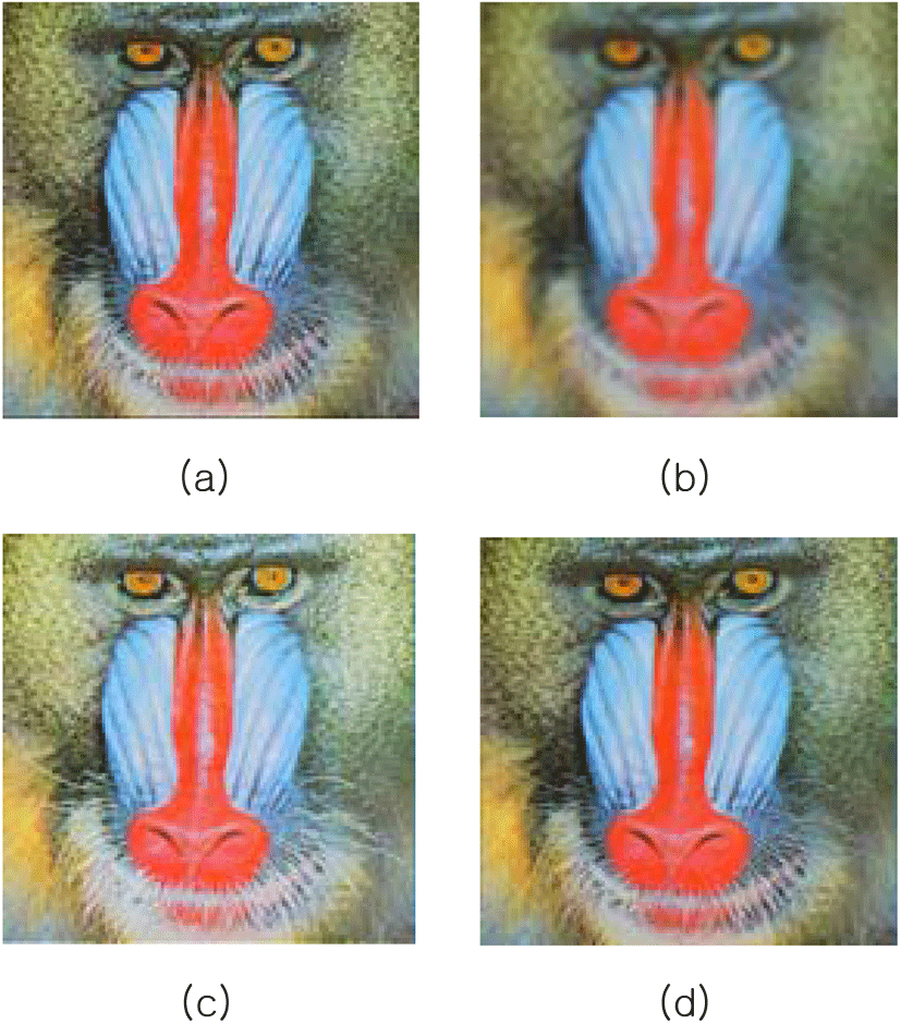
The blurring technique makes the image smoother. A typical blurring technique is Gaussian blurring using a weighted average filter, and blurring using an average filter. The weighted average filter gives a large weight to the mask intermediate value, and the lower the weight from the center. The average filter outputs the values in the mask as the average value of the pixel values. Blurring removes high-frequency components through low-pass filtering. Blurring has the advantage of eliminating image noise, but it has the disadvantage that it is blurred as a whole and the contrast ratio is weakened. To solve these drawbacks, bilateral filtering that can remove noise while preserving edge has been studied.
Image Sharpening is a method to improve the contrast ratio of images. unsharp mask, The Laplacian filtering, LOG, differential operator, etc., can be used to detect the edge and improve the contrast ratio by summing with the original image.
The Unsharp Masking (UM) technique is a technique to improve the contrast ratio by adding edge components to the original image. One of the image sharpening techniques is to remove the blurred image from the original image to obtain the unsharp mask image. The unsharp mask image removes the low frequency components and outputs only the high frequency components. Adding the original image and the unsharp mask image shows a sharpening image with an improved contrast ratio. The unsharp masking process can be expressed as Equation (1).
In the above equation (1), I′(x,y) is an image with an improved contrast ratio I (x, y) is an input image. H (x, y) is a high-frequency image for improving the contrast ratio and can be obtained by subtracting the blurring image from the original image. The filters used for the blurring images were weighted average filters. Using a weighted average filter, the higher the value of sigma, the stronger the blurring intensity. Adjusting the sigma value in the Gaussian distribution equation for UM plays a role in adjusting the high frequency component. The following figure 2 shows the UM technique as a signal.
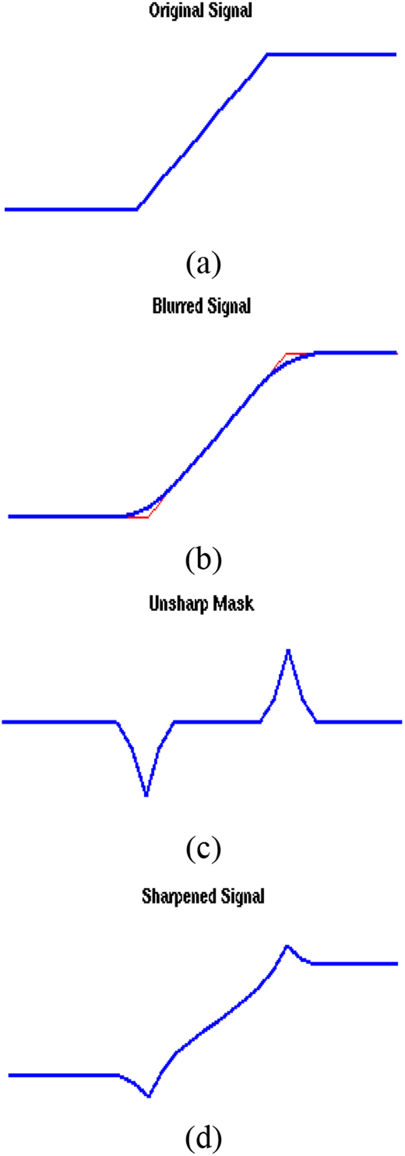
Figure 2 (a) shows the input signal. Figure 2 (b) shows the low-frequency signal, and Figure 2 (c) shows how the high-frequency component is left by removing the low-frequency signal from the input signal. Figure 2 (d) shows that the high-frequency component is added to the input signal to further emphasize the high-frequency component. The following Figure 3 shows the process of obtaining an unsharp mask image from an Image.
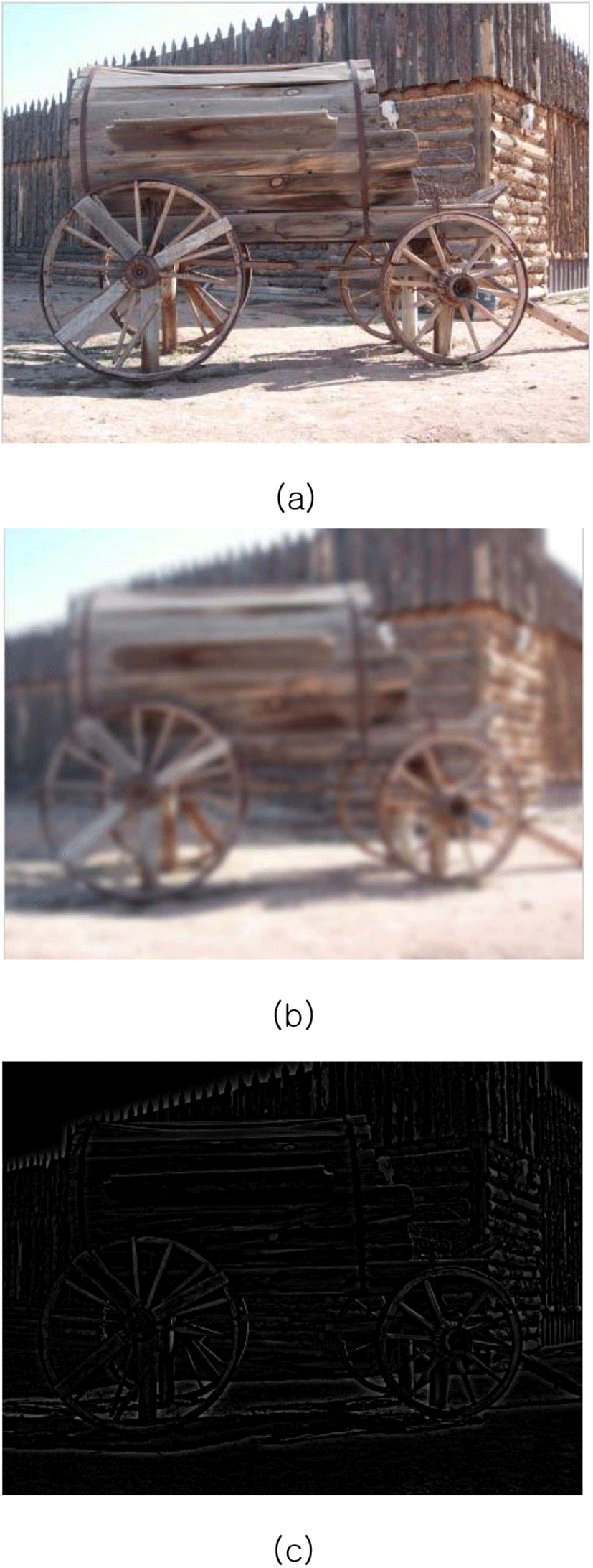
After obtaining the unsharp mask image, we can obtain the sharpening image with the improved contrast ratio by adding the mouth image and the unsharp mask image. Various algorithms have been developed for adaptive processing of such unsharp masking technique [15][16].
Retinex is a combination of Retina and Cortex. Retina is the retina, and Cortex is the cerebral cortex. When a human perceives an object through the eye, the eye simply receives the light reflected from the object. However, in the cerebrum, the eye considers the ambient lighting components and interprets them. The algorithm that has been studied based on this principle is Single Scale Retinex. Single Scale Retinex defines the function to obtain the ambient illumination with the most basic Retinex algorithm. The function is used to estimate the illumination component. The image is expressed by the product of the illumination component and the reflection component as shown in Equation (2). I (x, y) is finally obtained image information. R (x, y) and L (x, y) refer to the reflection component and the illumination component.
The Retinex algorithm is a technique to improve the image quality by reducing the influence of illumination. Expression (3) is based on the reflection component of Eq. (2). As introduced in the introduction, Retinex is an algorithm based on human visual perception model. In the Retinex algorithm using Weber-Fechner’s law, equation (3) is transformed again as in equation (4)
Equation (3) can be expressed by the following equation using the log subtraction rule and the surrounding function. Where S (x, y) is used to estimate the illumination component of the surrounding area. The * is the convolution symbol, which estimates the illumination component by convolving the original image and the surrounding function. The Gaussian function such as Eq. (5) is mainly used as a peripheral function. Where K is the normalization coefficient, and c is the Gaussian constant.
The final result of Single Scale Retinex (SSR) is normalized to a value between 0 and 255 in Eq. (5). Single Scale Retinex (SSR) uses only one peripheral function, so we get a very different result depending on the Gaussian constant value, so we need to set an appropriate Gaussian constant according to the input image. When the Gaussian constant is large, the difference between the bright region and the dark region becomes more clear, but the information of the boundary portion is lost, and the information of the bright region is lost much. The boundary is clear when the Gaussian constant is small, but the difference between the bright region and the dark region is not large.
In digital image processing, a filter passes only the frequency that it wants to pass through the image. That is, the pass frequency region can be controlled. Designing a filter and modifying or improving an image is called filtering. In order to check the frequency response of the filter in the image, a Fourier transform process is required. Fourier Transform is a process of converting spatial domain data into frequency domain data. Through the Fourier Transform, it is possible to analyze the frequency pass characteristics by checking the spatial filter as a frequency response. On the contrary, it is possible to analyze the frequency response and to design it as a digital filter with pass characteristics. Convolution of the filter in the image is equivalent to multiplying the Fourier transform function of the two functions in the frequency domain.
T−1 :Inverse Fourier Transform
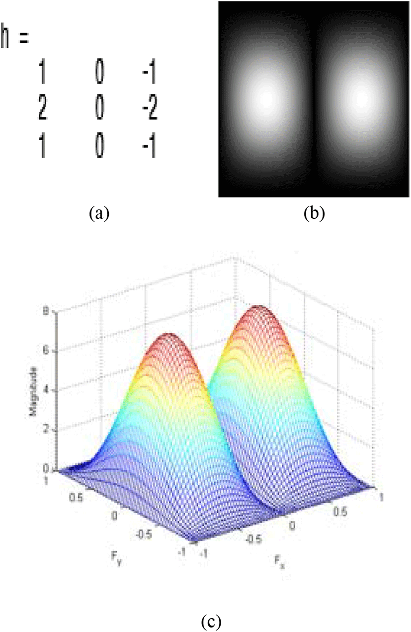
The processing of image and filter can be expressed as (10). The frequency response can be confirmed by Fourier Transform, and the digital filter can be designed through the frequency response. The figure below shows the result of Fourier transform of the Sobel filter and checking the frequency response.
III. PROPOSED METHOD
The algorithm proposed in this paper can be confirmed by Flowchart as shown in Figure 5.
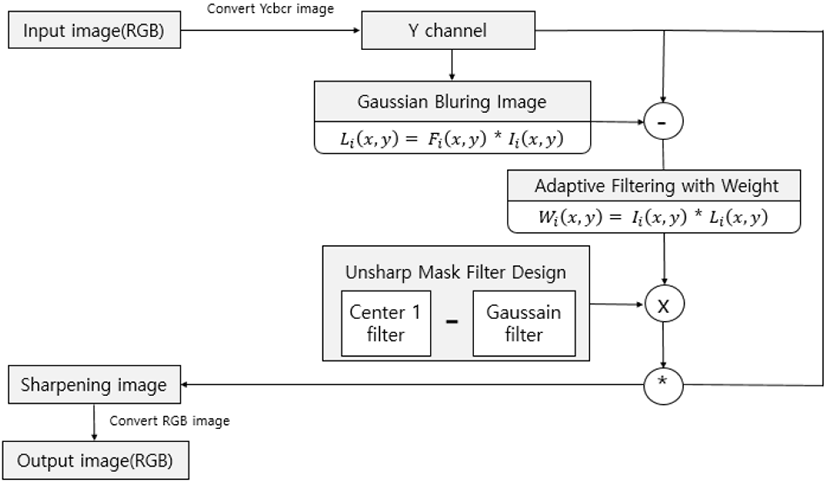
The specific contents of the algorithm are described in the following sections.
In this paper, the process of Unsharp Masking (UM) technique is designed as a spatial filter and processed by a single filtering operation. And the frequency response is confirmed by Fourier transform. The Unsharp Mask Filter (UMF) design can be obtained by the difference between the center 1 filter and the Gaussian filter. The spatial filter can be processed by multiplying the image in the frequency domain. In the process of designing unsharp mask filter, UMF can be obtained by subtracting the Gaussian Filter from the center 1 filter. In the next UMF, a filter with a center of 1 is added and filtering is performed. If you check the result image, you can see that the contrast ratio is improved than the input image.
The figure above shows the result of checking the filter when designing Unsharp Mask Filter (UMF). Figure 6 (a) shows the kernel with center 1, figure 6 (b) shows the Gaussian kernel, figure 6 (c) shows the UMF and figure 6 (d) shows the sharpening kernel. The UMF can be obtained by subtracting the Gaussian filter from the filter with center 1. On the contrary, the same result can be obtained by subtracting the filter with the center 1 from the Gaussian filter.
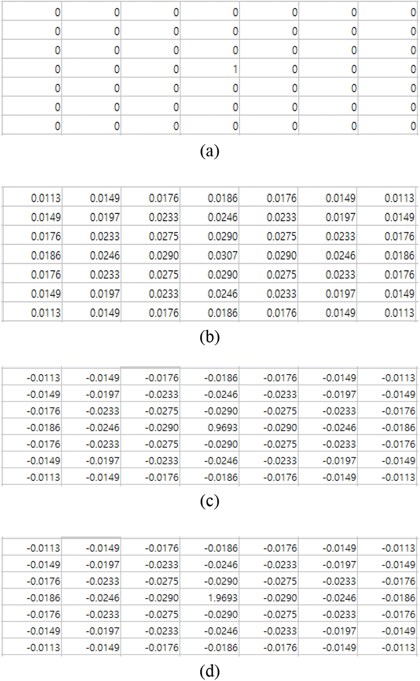
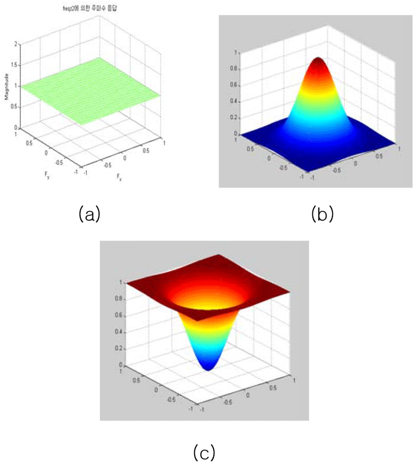
Figure 7 shows the design process of Unsharp Mask Filter (UMF) by frequency response through Fourier Transform.
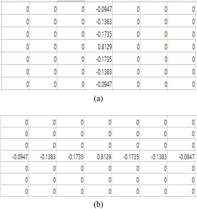
By designing the UMF and performing Fourier Transform, the frequency ranges to be passed can be confirmed and a new filter can be designed. The high-pass filter for emphasizing the edge in the horizontal direction in the image is Figure 8 (a). The high-pass filter for emphasizing the edge in the vertical direction is figure 8. (b). The frequency domain to be passed can be designed as a filter and the contrast ratio can be emphasized by the direction of the image.
We used Retinex principle to design Unsharp Mask Filter (UMF) and adaptive filtering. The principle of Retinex is used to control contrast ratio emphasis based on human visual perception model. Human vision is not well recognized when emphasizing the contrast ratio in the light-bright area, and better recognizes the contrast ratio emphasized in the dark area. By using this principle, it is possible to improve the weight ratio of the UMF in the dark area and the weight of the UMF in the bright area, thereby effectively improving the contrast ratio. Letting W (x, y) be the intensity for improving the contrast ratio and L (x, y) be the image information finally obtained as the illumination component, I (x, y).
The intensity W (x, y) of the contrast ratio is obtained by the difference between the image information and the illumination component. In order to obtain L (x, y) , a peripheral function S(x, y)is defined and estimated. The * used to find S(x, y) is the Convolution symbol, and the original image and the surrounding function can be obtained by Convolution computation.
The surrounding function S(x, y) is a normalization coefficient using the Gaussian function, and s is the sigma value controlling the size of the Gaussian function.
Finally, if the magnitude of the illumination effect is obtained by the image information, the intensity of the contrast ratio can be adjusted according to the size of the image information.
The strength of the unsharp mask filter is determined according to the finally determined W (x, y) and the result of the improvement of the contrast ratio can be confirmed. Different results can be obtained depending on the Gaussian constant value in the peripheral function. An appropriate Gaussian constant should be set. Figure 8 below shows an adaptively improved contrast ratio.
Figure 9 shows that the unsharp mask filter is more emphasized than the conventional method, and the emphasized images are naturally emphasized adaptively. Table 1 and Table 2 below show the PSNR and AMBE results of the Figure 8 images. The PSNR (Peak Signal Noise Ration) index is an index of the loss information of the image. The higher the PSNR, the less the loss. The AMBE (Absolute Mean Brightness Error) indicator shows that the smaller the average brightness difference is, the better the average brightness maintaining performance of the input image.

| PSNR | UM | Adaptive UMF |
|---|---|---|
| duck | 20.9016 | 21.7520 |
| Chariot | 21.8072 | 22.0377 |
| Cathedrals2 | 21.5105 | 22.9392 |
| Notredam94 | 20.3287 | 22.2292 |
| PSNR | UM | Adaptive UMF |
|---|---|---|
| duck | 0.0315 | 0.0025 |
| Chariot | 0.0415 | 0.0402 |
| Cathedrals2 | 0.1386 | 0.1291 |
| Notredam94 | 0.0283 | 0.0224 |
| Dog | 0.0447 | 0.0348 |
If we check the experimental results, we can see that the proposed method outputs better results.
IV. EXPERIMENTS AND RESULT
In this paper, Unsharp Mask Filter (UMF) is designed to improve the contrast ratio, and the contrast ratio can be emphasized by one filtering process. In the past, we used the method of finding differences between images using images and adding the differences. However, it can be processed at once using the proposed technique. We design a filter and check the frequency response of the filter through Fourier transform. A new filter can be designed to control the pass characteristics through the frequency response. By designing UMF and adjusting the amount of contrast ratio emphasis based on the Retinex theory, the image can be adaptively improved. In the future, we will study how we can make the weight of UMF by making it a mathematical function, and control not only the contrast ratio but also brightness information of image.


