I. INTRODUCTION
Vehicle to vehicle (V2V) communications can provide a great potential to enhance the driving safety, improve traffic flow, and address road side information. By communicating between vehicles, it is possible to give warnings to drivers and providing appropriate information for safe driving [1]. Future autonomous cars will communicate each other based on bidirectional communications techniques such as dedicated short-range communications (DSRC) and wireless access in vehicular environment (WAVE) [2-3]. Due to the problems spectrum congestion related to the existing radio frequency bands and vulnerability to multipath fading of DSRC and WAVE, alternative wireless communication technologies are urgently needed.
An optical camera communications (OCC) system is a new trend of optical wireless communication using an LED transmitter and camera receiver at visible light spectrum [4-7]. Recently, OCC technology has been attracting much attention in various fields because LED and camera are used in many applications. Because LED headlamp, tail lamp, daylight running lamp (DRL) and cameras are used to exchange OCC data, it is possible to recognize the surrounding situation of running vehicles and can replace V2V communications. OCC system implementation does not incur any additional costs to use OCC wireless links because it uses LED light sources and cameras already installed in the vehicle. Along with the advantages of OCC, several researches related to wireless communication in smart traffic systems based on OCC have been conducted recently [8], [9].
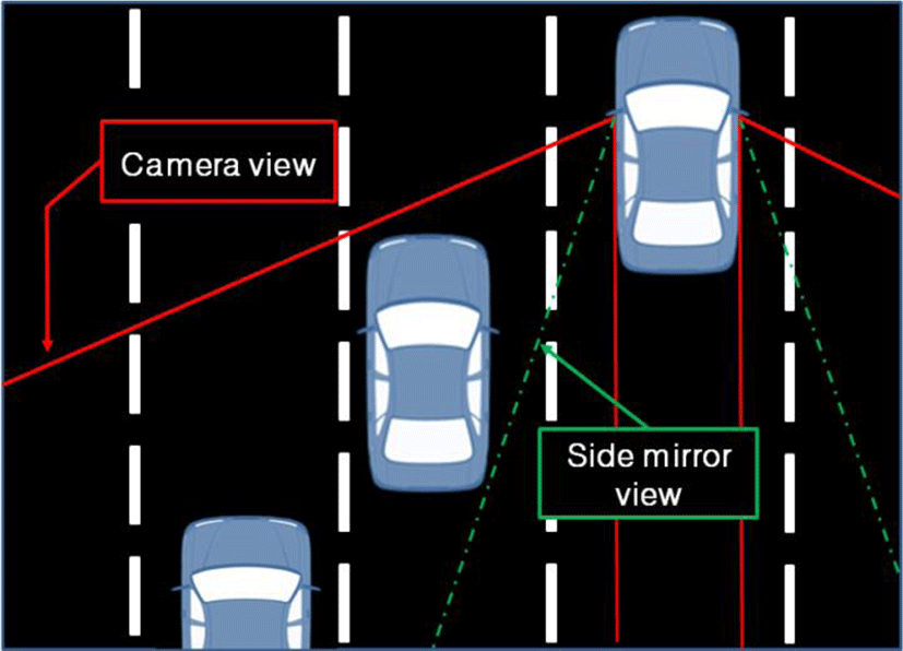
With the interests in new autonomous vehicles, new laws and regulations have allowed automakers to replace their existing side mirrors with rear side view cameras and monitors. In the mirrorless car with this system, the rear and side environment of the vehicle can be seen through the display device. As can be seen in Figure 1, the rear side view using the camera is much wider than that of the conventional side mirror, resulting in elimination of blind spots. Mirrorless vehicles with this system can provide safe driving because they can more easily identify potential threats or warnings based on camera monitoring systems. In addition, cameras are noticeably smaller than common side view mirrors and these mirrorless cars can provide clean external aerodynamics thereby offering a high potential to achieve improvement of effective fuel use for driving. Recently, Mitsubishi announced its technology that detects various object types at distances of up to about 100 meters [10]. In addition to these advantages, if the OCC data can be detected using a camera that can see the rear side of the mirrorless car, it can improve the stability of driving by complementing the problems of the existing V2V communication. Although an OCC approach using an optical communication image sensor (OCI) for inter-vehicle communication was previously studied, there is a limitation to use it widely because it is based on a newly designed structure of image sensors [8], [9]. As interest in mirrorless cars grows, there is still no research result that have applied OCC with a commercial camera to mirrorless cars in literatures.
In this paper, we address the OCC system for V2V communications based on mirrorless cars. The flicker-free light sources of DRL LED light sources were used to convey car’s action and vehicle type data to front cars. OCC data can be received by a camera located on the side of the front car via the wireless OCC link. Based on this, it is possible to prevent accidents by informing the front vehicle ahead of time when the rear vehicle overtakes or drives drowsy. The object of this paper is to evaluate the potential use of OCC-based V2V systems for mirrorless vehicles. In this study, we carried out experiments on OCC-based V2V communications using 4 types of vehicle action schedule, i.e. running, overtaking, cutting in, and caution, and vehicle type data at daytime and nighttime, respectively. Experimental results show that optical V2V communications for mirrorless cars can transmit OCC data successfully and can be an alternative technology for safety driving.
This paper is organized as follows. In section 2, an overview of system model of OCC technology is presented. Section 3 presents the experimental result of the OCC-based V2V. Section 4 addresses the conclusion of this paper.
II. SYSTEM MODEL OF OPTICAL CAMERA COMMUNICATIONS
In this section we first introduce the basic concept of OCC technology, followed by block structure of OCC system for V2V communications.
OCC technology is an image processing based technology that receives data sent by LED using a camera. By setting the camera to video mode and focusing the camera view on the LED, OCC data can be received. With the ability to be switched on and off at a very high speed, LEDs are used as the perfect light source to transmit data for OCC. Compared to the traditional lighting fixtures, LEDs have higher energy efficiency, smaller size, longer lifespan. Therefore, we are seeing a rapid installation of LEDs as light sources in homes, offices, vehicles, transportations, traffic and street lights and mobile phone.
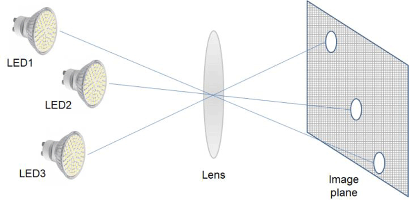
As a receiver that receives OCC data, OCC systems use cameras that are popularly used in many applications. A camera is composed of a photodetector (PD) array and a built-in readout circuit, which can be operated as a receiving side. The image lens mounted on the camera ensures that lights coming from different directions in the field of view (FOV) of the camera is projected at different positions on the image plane. As shown in Figure 2, a camera has a very high spatial resolution, which means that light coming from slightly different directions will be projected on the different locations of an image plane using a lens, and be sampled by different pixels. Because OCC data can be sent from different LED light sources located close to each other and are projected to different positions on the image plane, OCC data can be separately detected.
Safety applications in V2V communications must ensure very high reliability. However, wireless cooperation between vehicles can be a challenging problem due to the large amount of data exchange between autonomous vehicles. In recent years, there has been no other strong alternative to V2V wireless communications that uses radio frequencies. As LED lighting systems and cameras began to be used widely in transportation area, its usage for communications based on OCC technology becomes a strong candidate to conventional wireless communications in V2V. Moreover, a line-of-sight (LOS) link is essential for OCC data exchange, thus high reliability of data communication is ensured.
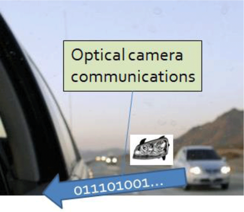
As shown in Figure 3, LED headlamps can perform multiple functionalities, i.e. illumination and communications, simultaneously. Because visible light spectrum is free to use and LED-based head lamps are equipped in modern cars, there is no additional cost to implement OCC systems for car applications. Using the advantages of OCC technology, it is possible to enhance the reliability of V2V communications. Furthermore, the potential of OCC technology has been confirmed with its standardization by the IEEE 802.15.7 standard [11]. Within the standard, the PHY I is intended for outdoor, long-range, low data rate applications such as including V2V communication.
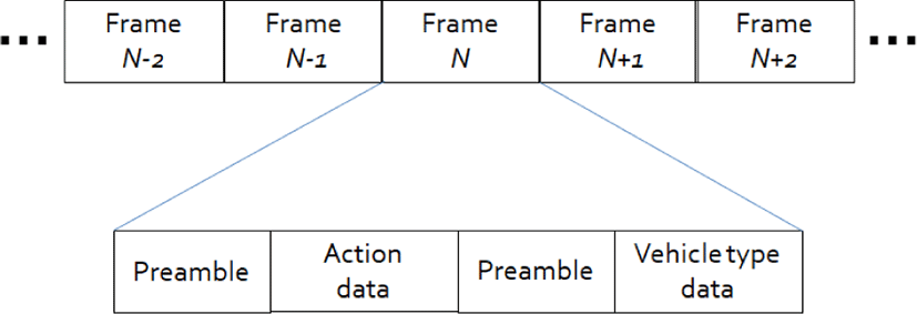
This section explains the process of data communications via the OCC link. LED light sources can offer both communication and illumination performance. Because the human eye cannot perceive the light pulses blinking at 200 Hz or higher frequency, a Manchester encoding method with a flickering rate of greater than or equal to 200 Hz was used. As shown in Figure 4, we set a data frame consisting of 8 bits of preamble and 16 bits of information data. In this study, we set the bit sequence of preamble as ‘10101010’. For information data, we consider two categories, ‘action data’ and ‘vehicle type data’. To provide enhanced productivity and convenience by freeing occupants from the responsibility of driving, vehicles should anticipate the action of other vehicles and collect information of the vehicle type. Using these data communications via wireless optical links, OCC systems ensures the safety of driving. As a transmitting LED source, daytime running lights (DRLs), which are used to increase the visibility of vehicles so that other drivers can see on the road, are used.
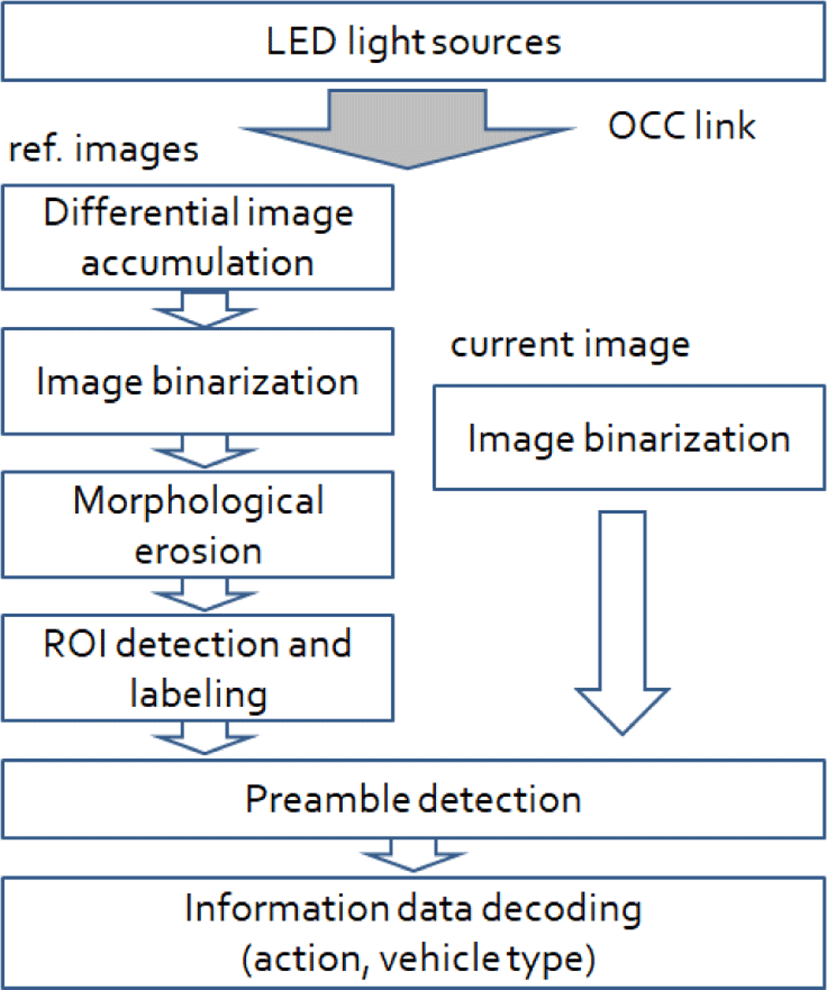
At a receiver-side, several blocks of image processing for extracting OCC data are considered. The block diagram of whole process is shown in Figure 5. A high speed camera, which is used as a receiver, captures images with both LED light sources and other light noises. To extract the image pixel regions containing OCC data, differential images are obtained and cumulated. An image binarization process is then performed using appropriate intensity thresholds. Figure 6 presents the result of image binarization at a different time. It can be seen that the variation of pixel intensity on LED light sources are observed. Based on this concept, OCC data can be extracted. To remove the additional noise induced by a camera equipped in a moving vehicle, a morphology erosion scheme is used. Then, region of interests (ROIs) containing OCC data are obtained and symbolic label are added to every ROIs. Because we set the same level of the camera sampling rate and LED flickering rate, a camera captures successive images containing “On” and “OFF” patterns of OCC data. By analyzing the intensity of ROIs in successive images, it is possible to acquire preamble and information bits, separately.
Using OCC-based V2V communications for mirrorless cars, it is possible to provide vehicle speed monitoring, collision detection avoidance, and object recognition. By employing DRLs as an LED data transmitter and camera as a receiver, OCC systems in V2V communications opens up new possibilities offering multiple functionalities including data communications.
III. EXPERIMENTAL RESULT
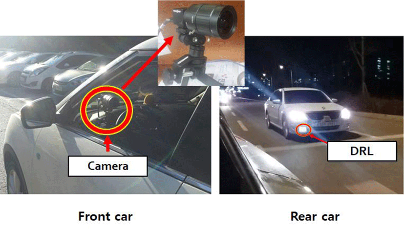
This section presents the test result of OCC-based V2V communications for mirrorless cars. In a V2V OCC scenario, a high speed camera was equipped at the mirror side in the front running car to receive OCC information. LED light sources of DRLs at a following car, running at rear and sides, transmits data containing the car’s action information (running, overtaking, cutting in, caution) and the vehicle type (compact, sedan, SUV, bus) information. A DRL is an automotive lighting device on the front of a roadgoing vehicle, automatically switched on when the vehicle is in drive, emitting white to increase the conspicuity of the vehicle during daylight conditions. Test environment using front running and rear running cars equipped with an LED transmitter and a camera receiver is depicted in Figure 7.
Table 1 shows test parameters of OCC-based V2V communications. The camera frame rate and LED flicker rate were set to 200 fps and 200 Hz, respectively. Image pixel size is set to 320 x 240. The vehicles run a speed of approximately 40 km/hr. Camera sensor type was global shutter.
| Modulation | Manchester encoding |
|---|---|
| Optical rate | 200 Hz |
| Frame rate | 200 fps |
| Resolution | 320 x 240 |
| Sensor type | Global shutter |
| Sensor format | 1/1.8” |
| Pixel size | 4.5 um |
For information data in a frame, bit sequences of action data and vehicle type data is presented in Table 2. To avoid flickering problem, Manchester encoded data was used for LED data transmission. It can be seen that the maximum length in which the same level appears continuously is 2.
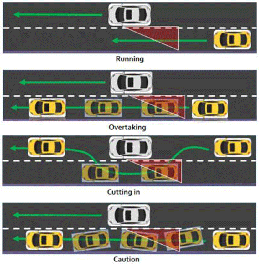
Figure 8 presents the test scenarios performed in this study. As can be seen in the figure, we have set up four scenarios for rear side vehicle movement. These four actions are representative action which is critical for safe driving of the vehicle ahead. If such an action information of the rear side vehicle can be known in advance by the preceding vehicle, it is possible to anticipate the action of the surrounding vehicle in advance and help the safe running. In this experiment, the data of future vehicle operation plan was transmitted from the LED light source of the rear side vehicle to the front vehicle via OCC link. At this time, not only the information about the action of the vehicle but also information about the type of the vehicle can be sent together to help a safer driving.
Figure 9 shows the results of testing on the real road. Experiments were conducted separately at daytime and nighttime to observe the effect of ambient light. In the figure, the left side shows the rear side vehicle observed from the front vehicle and the right side shows the simulator for analyzing the OCC data. In the simulator, we show four images obtained from the individual process of the block diagram in this study. It can be seen that the information about the vehicle action and the vehicle type from the rear side vehicle was successfully received. Note that the rear side vehicle started in a normal running state and the future action plan was sent to the front vehicle before the actual action.
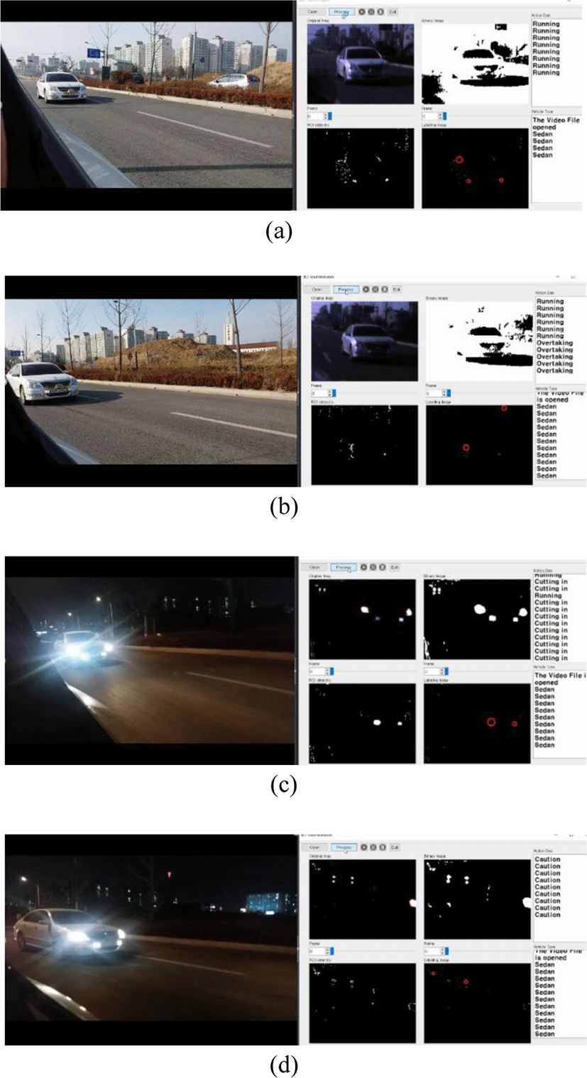
Table 3 shows the performance result obtained from the experiment. The maximum data rate obtained from the daytime and nighttime tests was 200 bps. The minimum frame arrival time required to obtain both the action data and the vehicle data was 240 ms. If a camera having a better frame rate is used or a diversity effect is obtained by using a plurality of light sources, the arrival time can be further reduced. The average processing time for decoding data was 0.1739 s and 0.1642 s for daytime and nighttime, respectively. Based on the experimental results, OCC based V2V communications for mirrorless cars can provide a viable solution to enhance driving safety.
| Daytime | Nighttime | |
|---|---|---|
| Maximum achievable rate | 200 bps | 200 bps |
| Minimum frame arrival time | 0.24 s | 0.24 s |
| Average processing time | 0.1739 s | 0.1642 s |
IV. CONCLUSION
In this paper, we have discussed OCC-based vehicle to vehicle communication experiments that can be applied to autonomous mirrorless cars. The camera is mounted on the existing mirror position of the vehicle to acquire future action information of the rear side vehicle, thereby assisting safe driving. The rear side vehicle transmits future action data and vehicle type data using a headlamp or DRL, and the front vehicle can receive OCC data from the camera and provide safe operation so as not to collide with the rear side vehicle. Experimental results show that OCC data is successfully transmitted during daytime and nighttime and proved that OCC-based V2V can be a strong candidate to enhance driving safety.


