I. INTRODUCTION
As demands for high-quality visual services are increasing, three-dimensional (3-D) information is widely used in various multimedia applications, such as free-viewpoint video (FVV), free-viewpoint TV (FTV), 3DTV, games, virtual reality (VR), etc. Since these applications try to provide consumers with depth impression and an immersion, the free-viewpoint navigation is becoming one of the essential functionalities [1]. View interpolation, view synthesis, and intermediate view reconstruction (IVR) have been important research areas to meet various requirements and needs for those applications. Moreover, they get more attention since multi-view display technologies are being developed rapidly nowadays.
As one of the intermediate steps to realize free-viewpoint applications, researches on multi-view systems are active recently. The multi-view camera system captures the same scene at different viewpoints. If we acquire multi-view images from multiple cameras, we can generate scenes at virtual view positions. It means that consumers can change their viewpoints and can feel visible depth with their view interactions. However, a viewing range depends on camera arrangements, the distance between cameras, and the total number of cameras. Most multi-view camera systems have confined configurations such as equally spaced one-dimensional (1-D) parallel, 1-D convergent, 1-D arc, two-dimensional (2-D) array, 2-D cross, etc [2]. Usually, parallel types are used to generate stereoscopic views since stereo matching can be employed easily. Moreover, it is easy to compress data acquired from parallel cameras because views are linearly correlated. While an arc or a convergent formation can provide a wider viewing range, occlusions cause problems.
Most view synthesis methods highly depend on regular camera arrangements even though they target multi-view displays or FTV. Those target environments, however, require more flexible viewpoint changes at arbitrary viewing positions. Conventional IVR algorithms assuming linear correlations between multi-views have limitations. It is necessary to synthesize virtual views in arbitrary camera arrangements in order to achieve natural free-viewpoint navigation.
The other problem is the number of cameras to meet the goal. It is well known that the quality of intermediate views improves as cameras get closer. It is not practical to set up cameras at all possible viewpoints, since the size of data increases as the number of cameras does. We need to reduce the number of cameras considering the visual quality of synthesized views. In order to resolve this problem, we use a hierarchical representation based on layered depth image (LDI) [3] using multi-view color and depth images [4]. Since 3-D information or approximate geometry can reduce the number of cameras, we can generate virtual views of tolerable visual quality with less number of cameras. Unlike the previous approach making a single LDI from all multi-view color and depth data [4], we select multiple reference locations using a clustering technique and generate multiple LDIs at those positions. Since the FTV system requires depth maps for every viewpoint [5], we assume that color and depth data are available for all cameras with camera parameters.
In this paper, we focus on the design of an intermediate view generation scheme for coding of multi-view color and depth data in arbitrary camera arrangements using multiple LDIs. The main contributions are as follows.
First, our view synthesis scheme can handle sparse number of cameras using a hierarchical representation based on LDI, constructed from multiple color and depth images. Unlike the proposed approach, most view synthesis algorithms depend on linear correspondences among dense cameras.
Second, our approach can generate synthesized views with the better visual quality than others, especially under irregular camera arrangements. It is less dependent on linear correlations between adjacent views. We select reference camera locations using a clustering technique. Then, we construct multiple LDIs at reference positions and generate a new view from the closest LDI to the selected viewpoint. Our scheme is also applicable to the regular camera arrangements since clustering techniques can be applied to any camera configurations.
Third, we can enhance the visual quality of reconstructed views comparing with the previous approach using a single LDI. Since the distance between cameras is far and many pixels are overlapped at the same pixel location, it is difficult to select proper pixels to fill holes. By reducing the number of active layers considering pixel distributions, we reduce artifacts and improve the coding performance.
Finally, the proposed approach is appropriate for immerging applications requiring free-view navigation such as FTV. We can synthesize intermediate views with a tolerable visual quality at arbitrary viewpoints while employing small number of cameras. Therefore, we can set up a FTV system cost-efficiently.
The rest of this paper is organized as follows. We briefly overview the FTV system, view synthesis algorithms, and multi-view video coding activities in MPEG in Section II. We describe our view synthesis and coding schemes in Section III. The performance of the proposed technique is shown in Section IV. The paper is concluded with some discussions in Section V.
II. REVIEW OF RELATED WORKS
In this section, we describe the FTV system, view synthesis techniques based on image-based rendering methods, and review multi-view video coding activity in MPEG.
Television consumers perceive a distant world in real-time and have been more than a display device. It has drawn the most important visual information and communications technologies up to date. However, consumers only can get a single view of a 3-D world with conventional TVs. The view is determined not by consumers but by a camera placed in the 3-D world. This is different from what we experience in our real world.
FTV is an innovative visual media that enables us to view a distant 3-D world by freely changing our viewpoints as if we are there. It has much potential since such as functionality has not been achieved by conventional TV technologies [6].
ISO/IEC JTC1/SC29/WG11 Moving Picture Experts Group (MPEG) has recognized the importance of FTV technologies. Since FTV was proposed to MPEG in 2002, there have been consistent efforts to realize it until now.MPEG issued a call for proposals (CfP) on 3-D video coding for high-efficiency video coding (HEVC) [7] in 2011. In 2012, MPEG and Video Coding Experts Group (VCEG) of ITU-T have started a joint collaboration on 3-D video coding extension (JCT-3V) [8].
FTV realizes free navigation of consumers due to its new function of view generation. FTV can generate views at infinite number of viewpoints from finite number of camera images. FTV is implemented as the real-time complete chain from multi-view capturing to free-viewpoint display. The consumer can freely control the viewpoint for a real dynamic 3-D scene. In order to achieve free navigation functionality, depth information is required in addition to video signals.
Figure 1 shows an example of FTV system that transmits multi-view video with depth information (MVD) [5]. The content may be produced in a number of ways with input sources from a stereo camera, a depth camera, a multi-camera setup, or 2-D/3-D conversion. At the receiver, depth image based rendering can be performed to generate multiple views adapting to various types of displays.
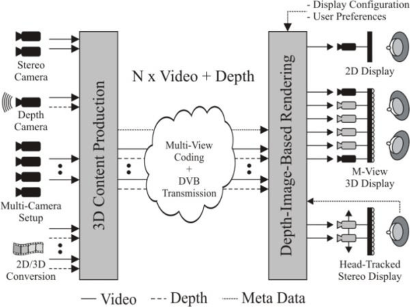
Image-based rendering (IBR) techniques have been proposed to generate new viewpoints with photorealism, perceptually indistinguishable rendering, using two or more images without heavy rendering of 3-D models or scenes. They use 2-D images as primitives to render an arbitrary view of the 3-D scene. In particular, their rendering time does not depend on the scene complexity, but rely on image resolutions. Various IBR techniques can be classified into three categories based on how much geometry information is used [9]: rendering with no geometry; rendering with implicit geometry; and rendering with explicit geometry. Since it has shown that the approximate geometry can improve the output visual quality and reduce a number of input images in [10], [11], there has been trade-off between the total number of image samples and the amount of geometry data used in IBR [9], [12].
Chen and Williams [13] reconstructed intermediate views by calculating pixel-by-pixel correspondences between input images. Their approach works on closely located images with high spatial correlation. Only synthetic scenes were examined in their experiments. Seitz and Dyer [14] proposed view morphing, which can generate 2-D transitions between two images. However, they choose corresponding line features between two images manually. Droese et al. [15] proposed a view interpolation method in disparity domain using a block matching algorithm. Since their approach use fixed block size, errors are caused in boundary regions. Recently, Lee et al. [16] modified this approach using variable block size and pixel-level disparity estimation. However, their method is only applicable to parallel camera arrangements.
As one of the intermediate step for FTV, an AHG on 3-D audio and visual (3DAV) has established in December 2001 [17]. Four main exploration experiments (EE) on 3DAV were performed from 2002 to 2004: EE1 on omni-directional video, EE2 on FTV, EE3 on coding of stereoscopic video using multiple auxiliary components (MAC) in MPEG-4, and EE4 on depth/disparity coding for 3DTV and intermediate view interpolation [18]. After MPEG called interested parties to bring evidences on MVC technologies in October 2004 [19], some evidences were recognized in January 2005 [20] and a CfP on MVC has been issued in July 2005 [2]. Through a series of efforts on multi-view video coding for several years, a CfP for HEVC-based 3-D video coding [7] issued in 2011.
Most multi-view video coding algorithms in MPEG focus only on reduction of data size of multiple color videos. They are based on the H.264/AVC video coding standard, a predictive coding scheme for a single video. Although numerous algorithms on 3D-HEVC efficiently reduce the size of multi-view texture and depth videos [21], they rarely use 3-D geometry information contained in multi-view video. In addition, they do not consider problems of efficient representation for multi-view data and coding of multiple depth sequences. In order to solve these problems, Yoon and Ho [4] proposed a framework and coding schemes of multiple color and depth video using a hierarchical data representation. In this approach, an LDI is generated for all multi-view data, so it has visual artifacts due to overlapped pixels at the same pixel location. In this paper, we try to reduce those artifacts and enhance the coding efficiency based on the proposed view synthesis and coding technique using multiple LDIs.
III. VIEW SYNTHESIS AND CODING OF MULTI-VIEW DATA IN ARBITRARY CAMERA ARRANGEMENTS
In this section, we explain the proposed intermediate view reconstruction algorithm based on a hierarchical representation. Since our approach is based on LDI, we first describe the concept, the generation procedure, and problems before presenting our algorithms in detail.
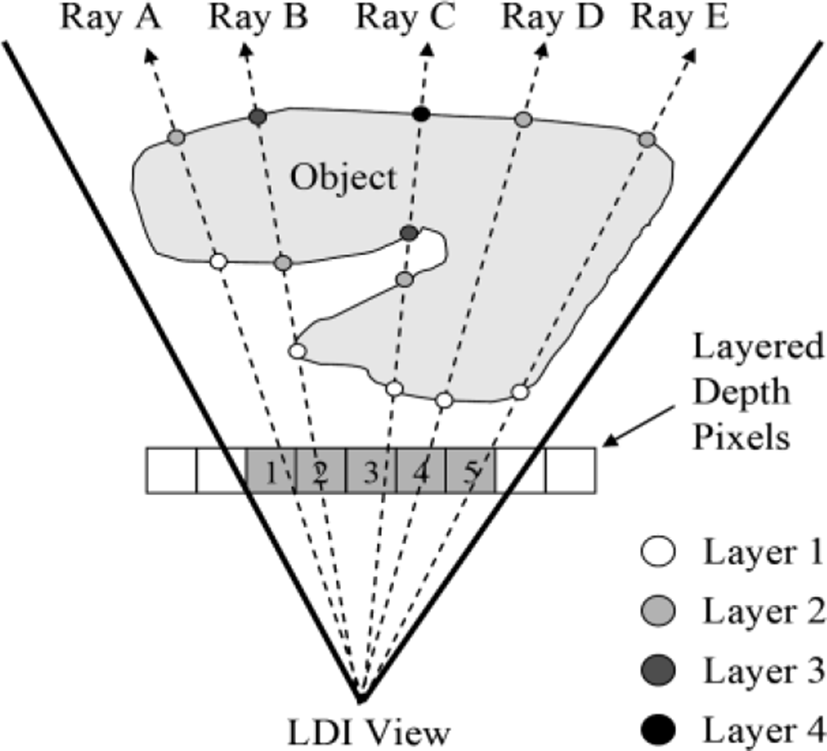
Among a variety of IBR techniques, LDI is one of the efficient rendering methods for 3-D objects with complex geometries. It represents the current scene using an array of pixels viewed from a single camera position. However, each LDI pixel consists of color, depth between the camera and the pixel, and other data that support rendering of LDI. Three key characteristics of LDI are: (1) it contains multiple layers at each pixel location, (2) the distribution of pixels in the back layer is sparse, and (3) each pixel has multiple attribute values [4]. Because of these special features, LDI enables us to render arbitrary views of the scene at new camera positions. Moreover, the rendering operation can be performed quickly with the list-priority algorithm proposed by McMillan [22].
When the rays are emanating from a reference viewpoint (an LDI camera), it is possible to store intersecting points between rays and an object. Each intersecting point contains color and depth information.
Figure 2 represents the conceptual diagram of LDI [4]. As shown in Fig. 2, the first intersecting points construct the first layer of LDI, the second ones build up the second layer, and so on. Consequently, each layered depth pixel (LDP) has different number of depth pixels (DPs), which contain color, depth, and auxiliary information for reconstruction of multiple views. For example, LDP 3 in Fig. 2 has four layers, which contain intersecting points between Ray C and the object [4].
Since rays cannot go through a physical object, this concept is applicable to computer graphics (CG) models only. Therefore, we generate LDI from multiple color and depth images using a 3-D warping technique [4]. Pixels of multi-view images are moved to the LDI view, a reference location, and then layers are created by comparing depth values at that camera location. In our previous approach, we have constructed a single LDI by warping pixels from all other views. For example, we perform 3-D warping for eight images to the reference location when we have eight-view color and depth images. However, this can cause many holes when the distance between cameras is far as shown in Fig. 3.
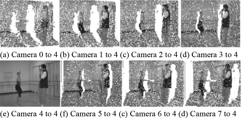
Fig. 3 shows the result of 3-D warping from other views to the reference camera for the “Ballet” dataset [23], [24]. The scene was captured from eight cameras with the 1-D arc arrangement. The distance between cameras is 20cm. In this example, we set the reference camera as the center one, camera number 4. There are lots of holes in the warped results because the distance from the left-most camera to the right-most camera is over 100cm. In the parallel camera arrangement, the distance between two extremes is even longer than the arc configuration.
In order to solve this problem, we separate cameras into several clusters and generate an LDI for each cluster in this paper. The first step is to assign 3-D coordinates to cameras so that we can treat them as 3-D vertices. Then, we divide those points into M (<Nmax, Nmax is the total number of cameras) clusters by considering minimum and maximum number of cameras. After constructing LDIs, we can generate virtual views selected by the consumer from the closest LDI to the views. Let us describe the procedures step by step.
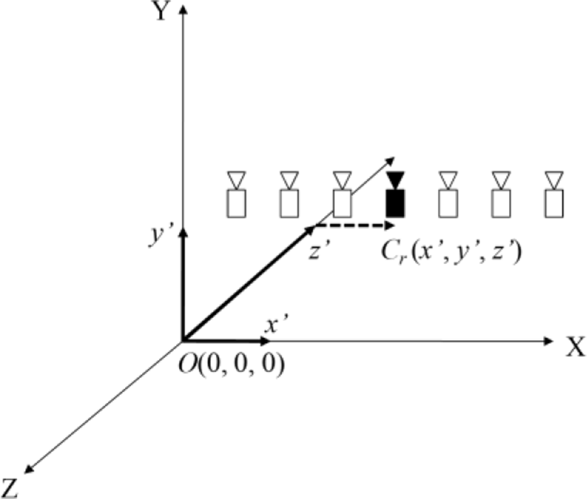
Extrinsic camera parameters present translation and rotation of each camera based on a reference camera. The reference camera is set when the scene is captured from a multi-view camera system. For example, if a camera in the center is selected as reference, relative positions of others are calculated by the camera calibration.
In order to convert relative positions to absolute locations in the 3-D space, we set the 3-D world coordinates. The position of the reference camera Cr is represented by
where O is the origin of the world space and D is the offset or displacement of Cr from the origin in XYZ coordinates. Then, the locations of other cameras Ci, i is the camera number, are calculated again in this world coordinates.
Figure 4 shows an example on how we set the world coordinates and the position of the reference camera. The basic assumption is that we already know the camera parameters for all cameras. Since the extrinsic camera parameters indicate relative translation of each camera from the pre-defined reference, we change the relative values to the absolute 3-D points in the 3-D world space. Now, we select new multiple reference cameras among those 3-D points, that have (x, y, z) values, using a clustering technique.
At this step, we partition 3-D points into M clusters. M is a natural number and the range of M is defined by
where M is greater than Nmin and less than Nmax. Nmax is the total number of cameras.
In order to determine Nmin, we need to examine the characteristics of LDI. One of the main advantages of using LDI is that LDI can resolve the occlusion problem by storing multiple depth pixels (DPs) at each pixel location [3]. Each DP contains color, depth, and auxiliary information. When we generate virtual views, the DPs in the back layers are used to fill holes caused by disocclusion. Although some areas cannot be covered by the DPs only, it is reasonable to collect pixels from other viewpoints and to use them for virtual view synthesis.
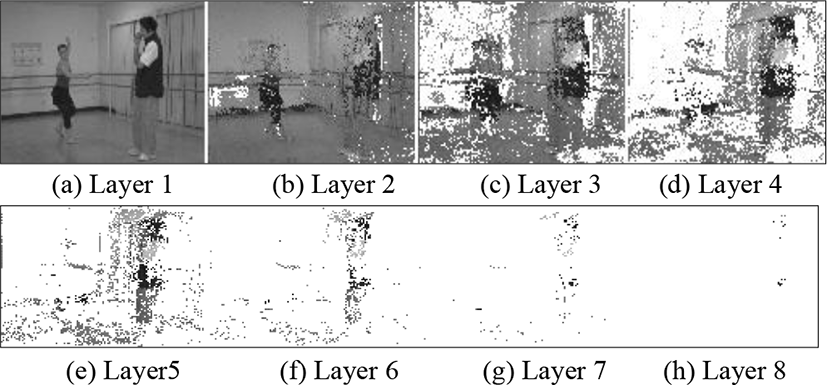
However, the problem is to select proper DP to fill the holes. If we have many DPs in the back layers, we should determine which one is appropriate for the current empty pixel. Table 1 lists the pixel distribution at each layer of the constructed LDI from the first eight views of the “Ballet” dataset.
| Layer | Pixel Occupation [%] | Layer | Pixel Occupation [%] |
|---|---|---|---|
| 1 | 100.0 | 5 | 15.8 |
| 2 | 99.0 | 6 | 5.0 |
| 3 | 68.2 | 7 | 1.1 |
| 4 | 38.4 | 8 | 0.1 |
Corresponding to Table 1, Figure 5 represents the layer images of the constructed LDI. From Table 1 and Figure 4, we can observe that the pixel distribution becomes lower than 50% after the third layer. Similar experiments performed before also show that the occupancy of pixels at each layer drops below 50% after the third or fourth layer [4], [25].
Those mean that the effective number of DPs that could be used to fill holes is up to three or four depending on the distance between cameras. In the case of the 20cm spacing, we need at least three views to construct LDI. Based on these experiments, we have set the Nmin as two for the “Ballet” and “Breakdancers” dataset [23], [24] and for the “Dooyoung” dataset [26], [27]. We describe the characteristics of the test data in our experimental section in detail.
Then, we partition the 3-D points into M clusters using the K-means clustering technique [28] based on the Eq. (2). If the partitioned cluster has two points, we add one more point nearest to the seed point of the cluster. Finally, the seed points after clustering are set as the reference locations to generate LDIs.
After we generate LDIs at multiple reference locations, we have to calculate camera parameters at the viewpoint of the consumer. First, intrinsic parameters of the selected virtual camera are interpolated as average values of those of cameras included in each cluster.
The translational component can be easily computed from the new viewpoint. Since we define all viewpoints and camera locations in the world coordinates, we can convert the 3-D location of the viewpoint to the relative camera position. The reference is already set by the partitioning and clustering in the early stage.
For the rotational component, we compute the single axis rotation angle between the reference camera and the newly selected virtual camera [14]. When the normal vector of the image plane of the reference camera is denoted as NR and that of the virtual camera is NV, the rotation axis NN and the angle θ between these two vectors is obtained by
The viewing range that can be covered by a single LDI is confined by that of input images. If we have an LDI constructed from the infinite number of input images at all viewpoints, there are no limits of viewing range. However, it is impractical to use a huge number of cameras and acquire depth information for all those views. Therefore, we need to assess proper viewing range of one LDI.
There are mainly two factors that can affect viewing range of the single LDI. One is the distance between cameras. As we mentioned before, the minimum number of input images to generate LDI can be changed based on it. The other is the performance of the hole filling technique used in LDI rendering. If we can fill dis-occluded areas within tolerable visual quality, the number of input images can be reduced further. Recently, Cheng et al. [29] proposed a hole filling scheme to reduce the effect of contaminated pixels from multiple DPs. If background colors are far different from foreground, visual artifacts occur at pixels along the boundary of objects because of contributions from both the background and foreground colors. Thus, they do not use the average pixel value of all DPs but that of clustered DPs.
However, we can remove those effects by generating multiple LDIs containing smaller layers. Experiments on pixel distributions show the rationale. Since we can find closest LDI to any viewpoint, whole areas can be covered by the proposed multiple LDI-based view generation approach.
IV. EXPERIMENTAL RESULTS
In order to examine the performance of the proposed scheme, we use the following multi-view datasets: “Ballet”, “Breakdancers”, and “Dooyoung”.
Figure 6 shows the test data used in our experiments. Figure 6(a) and Figure 6(b) are captured from eight cameras with 1-D arc arrangements. Figure 6(c) is an example scene captured from 16 cameras. The cameras configurations used to capture these test data are depicted in Figure 7 [23], [27].
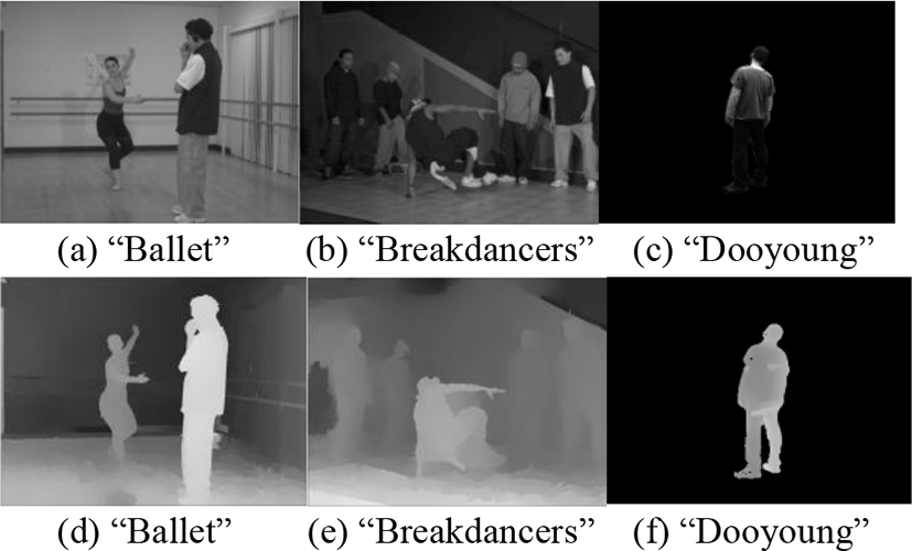
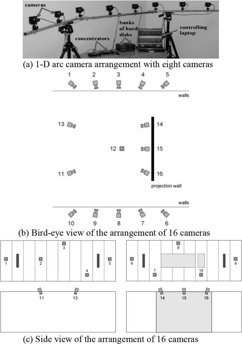
Figure 7(a) is used for “Ballet” and “Breakdancers”. Figure 7(b) and Figure 7(c) is for “Dooyoung”. The “Dooyoung” test dataset was captured from irregular camera arrangements with large spacing between cameras.
Figure 8 presents the clustering results of the regular camera arrangement, e.g., for eight cameras. Since we have set the minimum number of cameras for each cluster is greater than two in Eq. (2), cluster three has overlapped camera. In Figure 8, the left-most camera is camera 0 and the right-most one is camera 7. Cluster 2 and 3 share the camera 5. Figure 8 shows one of the clustering results, so other cameras can be shared also.
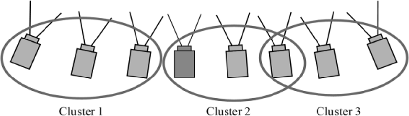
Figure 9 represents the clustering results of the irregular camera arrangement, e. g., for 16 cameras. Because of the viewpoint, camera 12 is not seen in Fig. 8. Camera 12 is clustered with camera 14, 15, and 16 together. Reference cameras of these clusters are camera 13, camera 4, camera 7, camera 9, and camera 15.
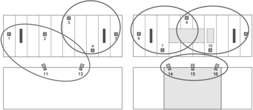
When the selected viewpoint is between two clusters, e. g., between cluster 1 and cluster 2 in Figure 7, we have calculated Euclidean distance between positions by
where D means the distance between camera positions, Cadj is the 3-D position of an adjacent camera and Csel is that of the new viewpoint. Then, we generate the virtual view from the LDI constructed in the closer cluster.
If the selected view is shared by two clusters, e. g., camera 5 in Figure 8, we compute the distance from the chosen view to the reference cameras of overlapped clusters. Finally, the view is reconstructed from the LDI generated from the cluster, which has closer reference camera.
Figure 10 shows the generated intermediate views between camera 0 and camera 2. The pictures in Figure 10(a) have been reconstructed from a single LDI, whose reference view is camera 4. Since the reference is far from these view positions, the results show visible artifacts in dancer’s hands especially.
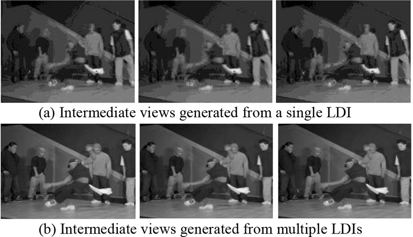
However, it is not easy to find noticeable artifacts in the results generated from multiple LDIs as shown in Fig. 10(b). In this case, the reference is camera 1.The center image is almost the same as the original view of camera 1.
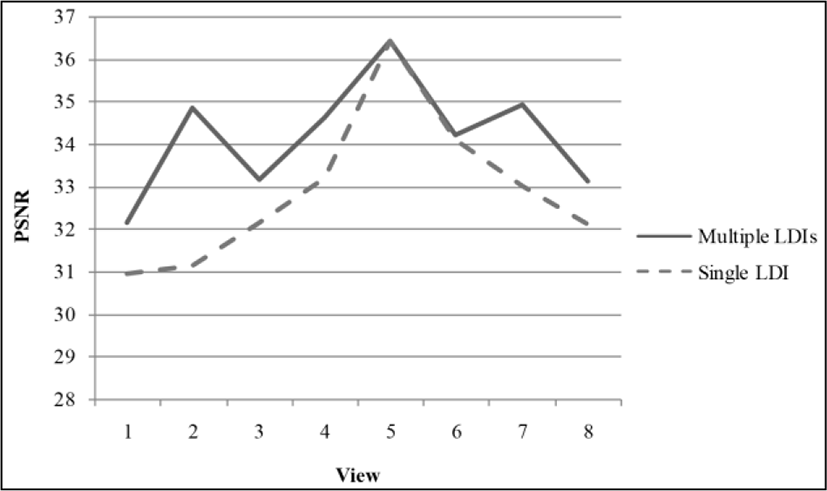
In Figure 11, we have compared peak signal to noise ratio (PSNR) for each view for two approaches: view generation from a single LDI and that from multiple LDIs. The thick line is the proposed scheme. As we can observe in Figure 11, the proposed approach shows better PSNR performance since it has multiple references. The PSNR reduces as the viewpoint is far from the reference camera location in the previous method using a single LDI.
In Figure 12, we have constructed the LDI from camera 6, 7, and 8. In most linear intermediate view generation algorithms, it is difficult to calculate linear relationships between those three views because they are not linearly located. Although the long distance between cameras cause visible artifacts, it is possible to estimate views at arbitrary positions within the triangle connecting three camera points. The reference camera is set by camera 7. From the LDI at the location of camera 7, we have reconstructed views at camera 6 and 8 as shown in Fig. 12.
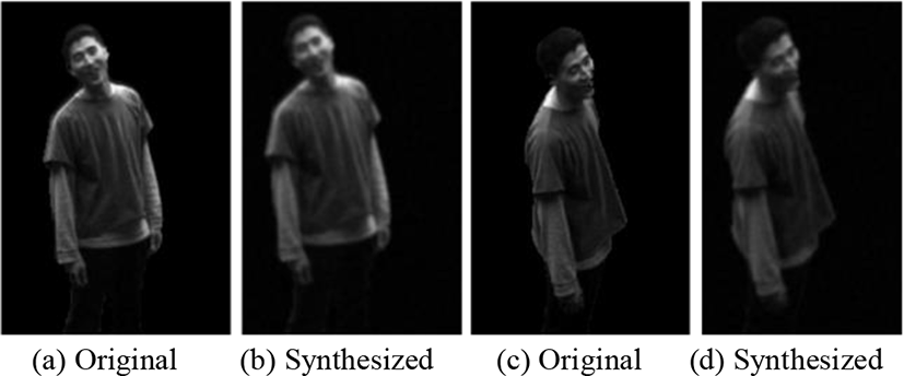
Figure 12(a) and Figure 12(c) are the original views at camera 6 and camera 8. Figure 12(b) and Figure 12(d) show the synthesized views from the constructed LDI at camera 7. Although the results are blurred a little, subjective qualities are acceptable.
In addition, we have compared the objective quality for the existing views in terms of PSNR. Since we have the original view 6 and view 8, we can compute PSNR between the original views and the synthesized ones from the proposed approach. PSNR of Figure 12(b) to Figure 12(a) is 31.23 dB and that of Figure 12(d) to Figure 12(c) is 30.52 dB. Since the warped object is not aligned in the same location of the original view, the PSNR is rather low. However, subjective visual quality is tolerable as depicted in Figure 12.
In order to show that the proposed scheme has benefits in terms of coding, we have shown comparison results in terms of PSNR Y vs. bitrate for the “Breakdancers” sequence in Figure 13. The proposed method is compared with the previous approach using a single LDI and other MVC schemes [4].
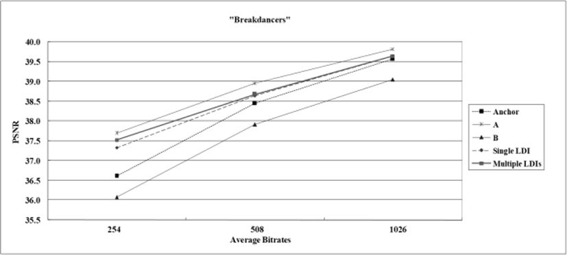
The important fact in Figure 13 is that all other methods encode color components only, but the proposed one compresses color, depth, NOL, and residual data. In other words, the PSNR curve in Fig. 16 for the proposed method is the result of the total bitrates for depth, NOL, and residual as well as color data. However, the other curves present the PSNR Y vs. bitrate for the color component only. The coding results are displayed for three rate points: low, middle, and high bitrates [4]. In Figure 13, the anchor means that all views are encoded separately using H.264/AVC with specified parameters [2]. All PSNR curves represent the average values over all views.
As shown in Figure 13, we can observe that the proposed approach based on multiple LDIs shows better coding performance than that of using a single LDI. For the LDI data, the same encoding scheme as the case of the single LDI has been used in this experiments. We have taken the average of three LDIs for the “Breakdancers” sequence in this experiment.
In order to show that the proposed scheme has benefits in terms of coding in irregular camera arrangements, we have shown comparison results in terms of PSNR Y vs. bitrate for the “Dooyoung” sequence in Figure 14. We have compared our approach with the previous approach using a single LDI. The selected views are view 6, 7, 8, 9, and 10 since we have synthesized those views in Figure 12. The total number of frames is 100. The curves represent the average PSNR for 100 frames at each bitrates. The other coding conditions are the same as the case of Fig. 13.
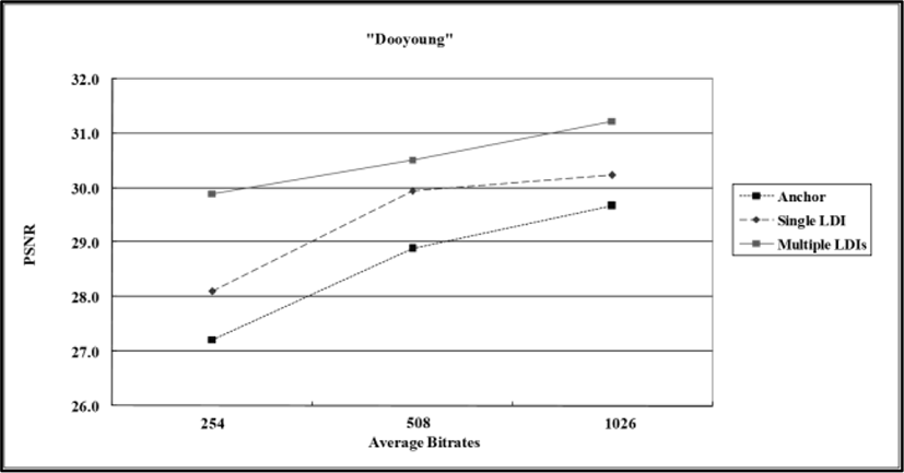
In Fig. 14, joint multi-view video model (JMVM), the reference software released by MPEG [30], has been used as the anchor. As shown in Fig. 14, the proposed scheme shows better performance in terms of PSNR. The improvement is about 1.8 dB on average at low bitrate for this test sequence.
V. CONCLUSION
In this paper, we have proposed a new view synthesis technique for coding of multi-view color and depth data in arbitrary camera arrangements. We treat each camera position as a 3-D point in world coordinates and make clusters of those vertices. Color and depth data within a cluster are gathered into one location using a hierarchical representation based on the concept of layered depth image (LDI). Since the viewing range covered by a camera is limited, we set numerous reference positions where multiple LDIs are generated to cover the whole viewing range. Therefore, we have enhanced the visual quality of the reconstructed views from multiple LDIs compared with that from a single LDI. From experimental results, the proposed scheme has shown better coding performance under arbitrary camera configuration in terms of both objective and subjective visual qualities. The improvement was about 1.8 dB on average at low bitrate for the test sequence captured from the irregular camera arrangement.