I. INTRODUCTION
Weather radar is used as a device to observe meteorological phenomena with higher spatial and temporal resolution in comparison with other equipment within observable distance. Recently, meteorological studies using dual-polarization radar systems of S and X band frequencies have been actively performed [1]. However, high spatial and temporal resolution means that the amount of data to be processed increases accordingly. Especially in the case of ground-based weather radar, various data are continuously accumulated because various parameters are generated while carrying out continuous observation [2], [3]. Furthermore, in order to utilize such data in the hydro-meteorological system, it is necessary to process various methods by preprocessing radar data such as quality control. In particular, a lot of computations are required to convert from a polar coordinate system to a realistic coordinate system having a desired spatial resolution. This coordinate system conversion process is a basic and important process because it can be a factor to measure the accuracy of radar precipitation rate over the ground rain gauge [4], [5]. In this paper, we propose a real-time coordinate conversion method of radar data to increase the usability of the weather radar.
The paper is organized as follows: section 2 reviews the background of weather radar data coordinate conversion and section 3 describes the proposed method in detail. Section 4 demonstrates the performance evaluation via simulation of the proposed method. Finally, section 5 summarizes the proposed method and details the advantages.
II. BACKGROUND OF WEATHER RADAR DATA CONVERSION
Data generated from meteorological radars introduced up until recently are mainly distributed to users in UF and NetCDF formats. These radar data will be matched to the GIS for radar calibration, weather analysis and forecasting [6]. And for more accurate calibration and weather analysis, correct real-world coordinate system conversion from the radar data is required. This paper proposes a method which reflects well the real-world coordinate system and changes the number of adjacent gate samples used in interpolation according to the distance to the variable as improving the coordinate system transformation algorithms included in the software such as SPRINT [7] and REORDER [8]. Each interpolation window for the SPRINT and REORDER coordinate system transformations using radial ray profiles is plotted from Figure 1.
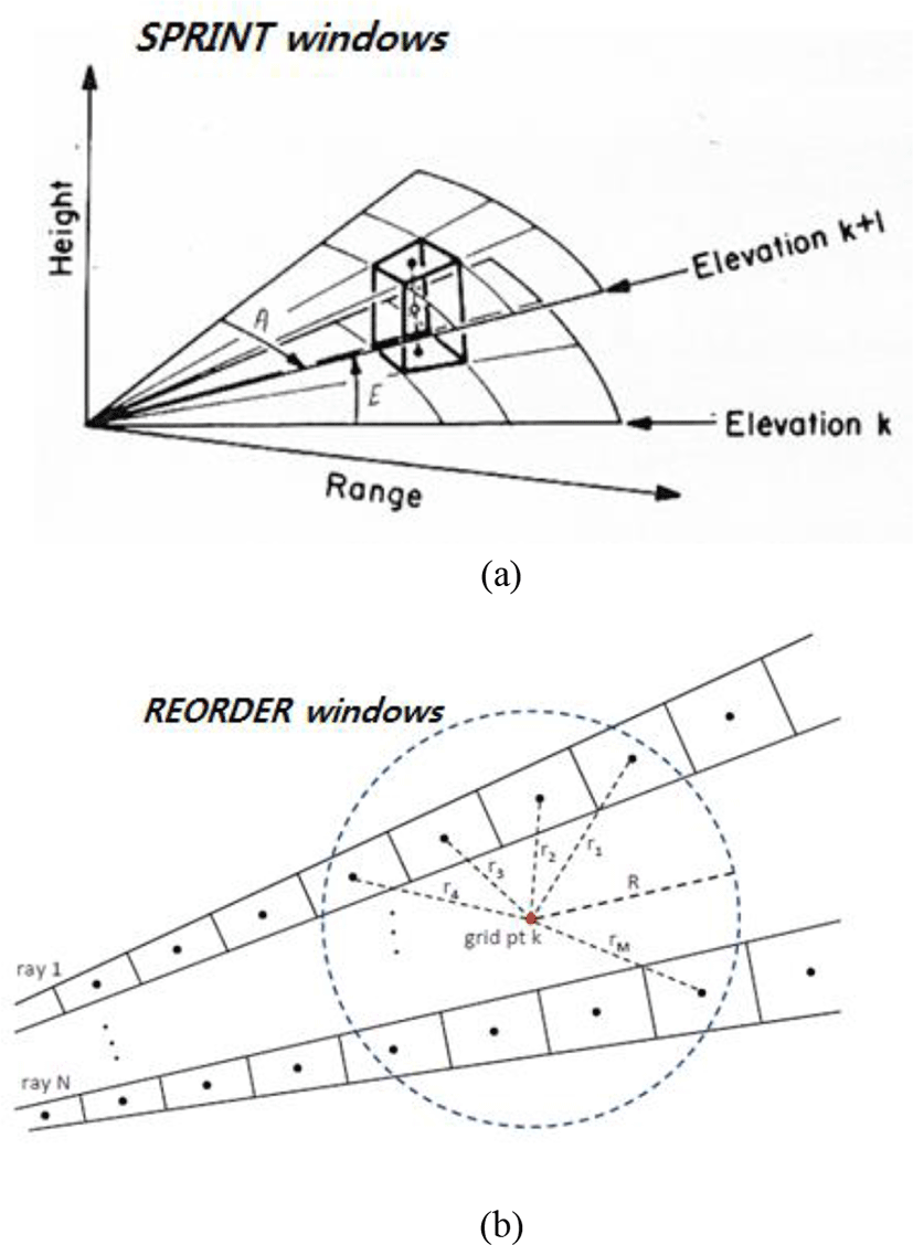
The interpolation masks shown in Figure 1 are schematically shown in Figure 2 as the ray profiles used for interpolating arbitrary coordinate points on the realistic coordinate plane.
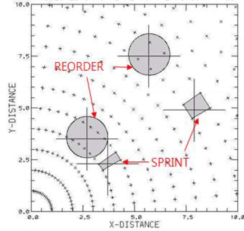
Figure 3 shows an example of performing coordinate system conversion by applying SPRINT and REORDER.
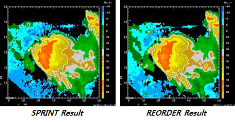
In the example in Figure 3, the result of REORDER appears to be a softer image overall than the result of SPRINT. This is because REORDER uses all samples in the interpolation mask radius because SPRINT interpolates using four data samples in the plan view. REORDER, on the other hand, interpolates by applying distance weights between all samples in the interpolation mask radius and the target coordinates so that the computational complexity is higher than SPRINT.
However, since both methods use interpolation method after sampling in consideration of the spatial resolution required in the actual coordinate system, the higher the resolution of the radar itself, the more difficult it is in real-time.
III. PROPOSED FAST COORDINATE CONVERSION METHOD
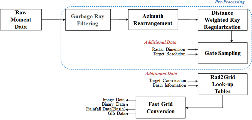
The proposed scheme combines the advantages of the interpolation masks of SPRINT and REORDER to use tables of predetermined radar samples for each interpolated object coordinate and also distance weights for each precomputed sample. This minimizes the process of finding the radar samples used to interpolate complex computation processes and target coordinates, thereby reducing computational complexity and enabling real-time radar processing. Figure 4 shows the implementation of the proposed method as a block diagram.
Korea Meteorological Administration(KMA) and the Ministry of Land, Infrastructure and Transport (MOLIT) radars are generated and distributed in UF format, and the data distributed is normalized to one ray profile per 1° for 360° azimuth in the polar coordinate system. On the other hand, the data generated from the current Seoul metropolitan X-band radar network is the original moment data of NetCDF format. The proposed method generates a lookup table by generating the parameters of the coordinate system transformation algorithm applied to each coordinate of the realistic coordinate system, and then applies a method of improving the operation speed of the coordinate system transformation applicable to both formats using the lookup table.
In order to use the coordinate system conversion look-up table for the radar variable samples in the predetermined polar coordinate domain, a preprocessing is required to generate a 1° azimuthal ray profile on the non-normalized raw radar data of the X-band radar network.
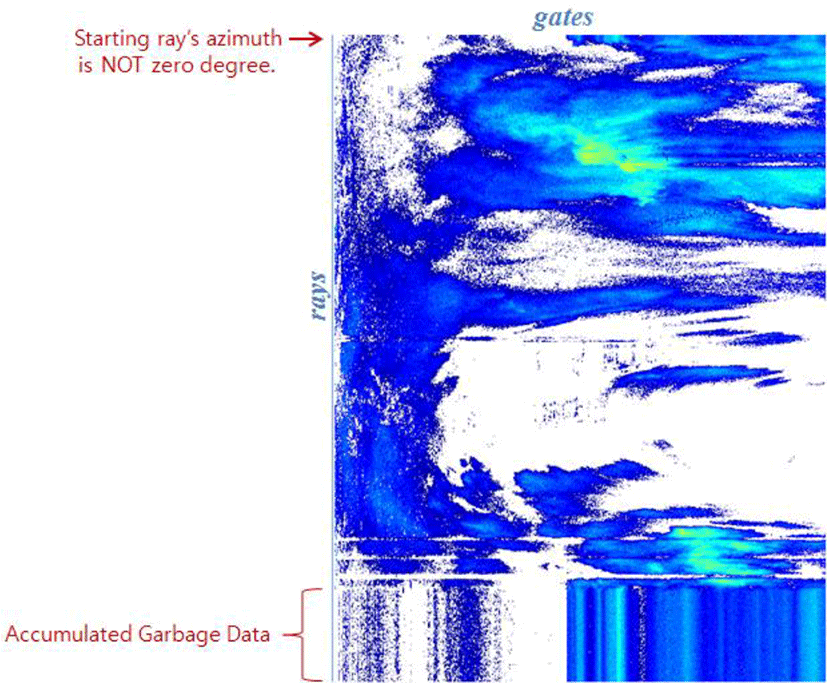
Figure 5 shows the ray profile of non-normalized radar data. As can be seen in Figure 5, the first ray of non-normalized radar data can be determined at an arbitrary azimuth from the radar observation starting direction. also since the observation data of the same azimuth angle is continuously input by the waiting time at the radar observation end point, garbage information may accumulate in the radar data.
In this case, since the lookup table of the proposed method can not specify the ray and gate index used in the interpolation in the target coordinates, the preprocessing process as shown in Fig. 6 is required.
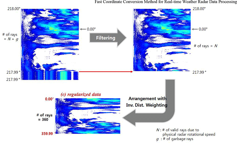
Figure 6 shows an example in which the preprocessing process of Figure 4 is performed. From Figure 6, we show the procedure and results of the original radar data and surplus ray filtering and azimuth rearrangement, respectively.
First, raw data with 813 ray profiles scanned for all azimuth angles, starting at an arbitrary azimuth (218°), are shown in Figure 6 (a). And Figure 6 (b) shows the results of 719 effective ray profiles after filtering the garbage rays using the each ray profile’s azimuth information of this data. Each ray profile has its own scan start and end azimuth information, and can be easily filtered using changes of these azimuth information – rays with little or no angular variation are considered as the garbage rays.
Next, the filtered ray profiles of Figure 5 (b) are rearranged in the order of azimuth angle 0° to 359.9°. We then use the inverse distance weighting technique to find values at azimuth angles of exactly 0.0, 1.0, 2.0, and so on, and perform sampling with 360 ray profiles. Finally, we generated 360 normalized ray profiles starting from the 0° azimuth through an inverse distance weighted sampling process as shown in Figure 6 (c). The coordinate system transformation is performed by mapping using the pre-calculated parameters stored in the lookup table corresponding to each coordinate point in each real-world coordinate system, using the normalized ray profiles as shown in Figure 6 (c).
The output resolution of the desired radar image, meanwhile, can be determined through a gate sampling process on the ray profile. For example, for 150 km of radar data having 1200 gates with a distance resolution of 125m per gate, a radar image with 600 gates at a distance resolution of 250 m can be calculated by performing 1/2 sampling before the coordinate system transformation
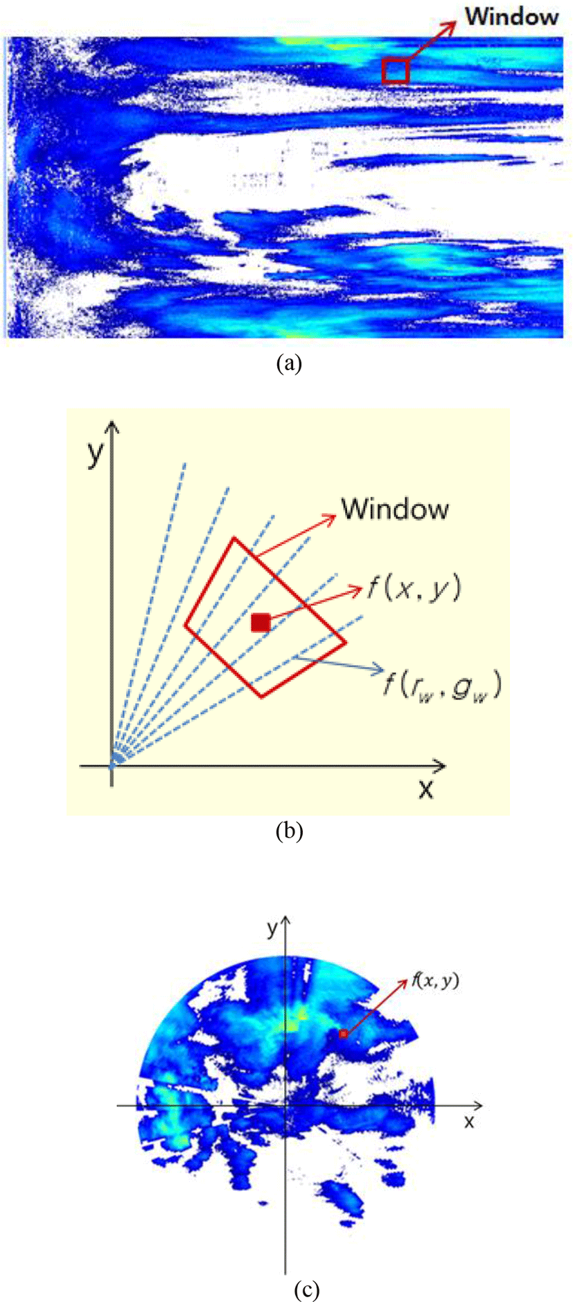
Figure 7 shows the results of the interpolation and the coordinate system transformation using the lookup table for the normalized ray profile of Figure 6 (c).
The concept of the interpolation mask of the proposed method is shown in Figure 7 (b). The square window of SPRINT was applied to the mask of Figure 7(b), and we aimed to improving the quality of radar data by applying the distance weight of REORDER at the same time. Also, by varying the window size according to the distance from the origin-center point of the radar(increasing the window size as the distance increases), we have minimized degradation of interpolation quality at a point far from the radar.
Every coordinate point f(x,y) in each realistic coordinate system has its own lookup table M(x,y). By preliminarily calculating and storing these sets of lookup tables, the computational complexity of the radar coordinate system transformation using eq. (1) can be minimized. Using this method, we can compute a set of lookup tables of sufficiently large size, and it is advantageous to convert all radar data with different radii to only one lookup table as shown in Figure 8.
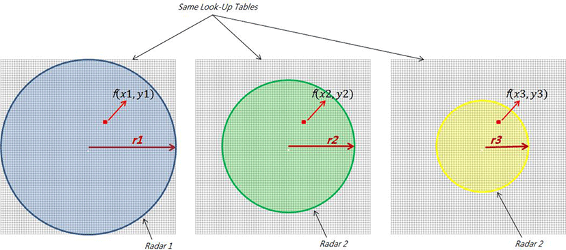
This is because the lookup table is calculated on the basis of the radar origin and therefore, for f(x1, y1), f(x2, y2) and f(x3, y3) represented by different coordinate positions on each radar in Figure 8, the same lookup table M(f(x1, y1)) can be used by the radar with the largest radius is f(x2, y2) and f(x3, y3).
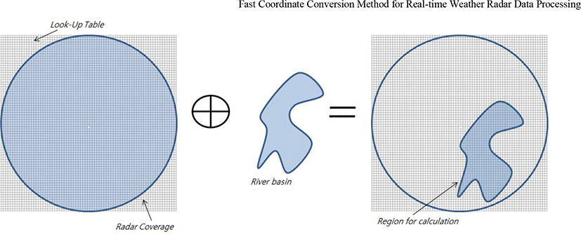
For the same reason, by using GIS coordinates or river basin(or watershed) information as a mask for the lookup table, radar images can be expressed in a desired global coordinate system, or only weather and precipitation information for the watershed can be extracted. An example is shown in Figure 9.
IV. SIMULATION RESULT
For the performance evaluation of the proposed method, we compare the method of applying the proposed method to the NetCDF data of the X band radar requiring the preprocessing process and the normalized UF data of the S-band radar of MOLIT. The simulation environment applied for the experiment is Intel Core i5-6200U dual core, 8GB RAM and SSD equipped laptops. Table 1 compares the processing speed of the proposed method using look-up table mask and not.
| Conditions | Proposed | None |
|---|---|---|
| UF(1200*360) | 1.02 sec. | 34.51 sec. |
| NetCDF(670*813) | 1.57 sec. | 23.37 sec. |
In general, the processing speed when converting the coordinate system is proportional to the number of gate cells (or distance resolution) (when the proposed technique is not applied). Therefore, as shown in Table 1, it can be seen that the processing speed is much faster although the number of gate samples (670 * 813) of NetCDF is larger than UF (1200 * 360).
The other hand, when the proposed method is applied, we confirmed that the coordinate system transformation is performed within 1 to 2 seconds for both data.
Considering that the minimum radar observation period is 15 to 30 seconds in general, it can be said that the real-time property is satisfactory in terms of radar data processing. In the proposed scheme of Table 1, although the NetCDF has far fewer number of distance samples than UF, it has been confirmed that the processing time is longer than that of UF as the azimuth normalization process is performed.
In case of UF, there is no need for a separate pre-processing process, so that deterioration of image quality does not occur even if the proposed method is applied. However, since the NetCDF generates a ray sampling effect during the azimuth normalization process, deterioration of image quality may occur. Therefore, we compared the result images of the coordinate system conversion using LUT mask and not performed on the NetCDF data from Figure 10.
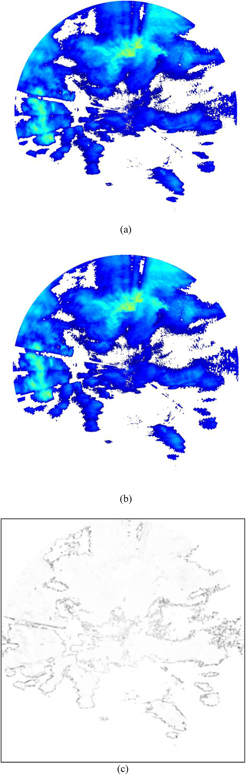
Figure 10-(c) shows the difference between Figures 10 (a) and (b). This is the blurring error that occurs in the ray sampling process in Figure 1 and shows an average error of 0.4 dBZ based on the radar reflectivity. This is included in the tolerance range in the radar weather analysis, and it is confirmed that the proposed technique can be offset from the advantage of having a processing speed of 15 to 30 times or more the maximum from Table 1.
V. CONCLUSION
Experimental results show that our method improves the computation speed more than 20~30 times compared with the conventional method and shows that the deterioration of image quality is almost negligible. By applying the proposed method, real-time prediction of flash floods and meteorological disasters using weather radar can be performed, and the efficiency of the short-term weather prediction can be improved. Also, by using the river basin information and the lookup table of the proposed method for estimating the watershed precipitation, we confirmed that it is possible to extract the results in a short time by extracting only the watershed area on the lookup table without converting all the radar images into the coordinate system. The proposed method is based on a small radar with a narrow observation range, and does not consider the observation altitude error according to the curvature of the earth. In the future, we plan to design more accurate coordinate conversion considering radar observing altitude according to the curvature of the earth for the application of large radar.