I. INTRODUCTION
The three-dimensional movement of hand with respect to wrist joint can be classified into one of four categories by assumed direction – flexion and extension (FE), and radial and ulnar deviation (RUD). Among the various joints of the body, wrist joint is one of the most complex structures, with its 15 bones including the distal ends of the radius and ulna. But measurement of the extremes of flexion-extension and radioulnar deviation of the wrist joint provides a limited picture of the static ability of the joint to move in the orthogonal planes. It also is difficult to ascertain the relationship between function of a complex joint like the wrist and these 2-dimensional measurements [1], [2].
Currently, a most common way of measuring wrist’s full range of motion includes goniometer. Data is read directly from the device, which is adjusted accordingly on the subject’s body. The advantages of this method include maximal portability and high accessibility due to its small-scale and light weight. It is the least expensive option for measuring joint movements, with cost in the range from about 5 USD to 100 USD1 [3]. Recently, smartphone goniometry applications have become available to clinicians, with error range of only about 1.7 degrees which is comparable to that of data gathered from prevalent goniometry [4]. A disadvantage of goniometer is its rather low level of accuracy. Since the accuracy of goniometry measurement is dependent on a host of factors such as variations among different subjects, methods of application, differences among the kinds of motions measured, and individual deviations by clinicians gathering the data, it is often hard to meet expected level of accuracy using goniometer [5]. The center of the bone is the ideal point to place devices on for measuring FE and RUD motions but goniometer alone, it is impossible to pinpoint the ideal point of measurement. Measuring is performed with the device on the surface of the arm, which is constantly affected by several factors including muscle and skin contractions. This is also the reason why recently-released digital type goniometers are not considered accurate either. Another disadvantage of goniometer is that real-time tracking of motion is impossible. This discourages its use in the fields such as robotics or virtual-reality (VR).
The reason the tool is widely used even with such a high error range is because a difference of ± 10 to 15 degrees in range of motion (ROM) over time does not signify a meaningful change when it comes to comparatively examinations of patients [5].
Among the various apparatus for measuring ROM, another well-known one that overcomes these flaws is the three-dimensional (3D) motion capture system. High accuracy of this system has been proved by several previously released studies [6]. A 3D motion capture device, specifically Optitrack, coupled with Micron Series calibration tools, can produce fairly precise measurements down to sub-20μm tolerance. It may be possible to set the measuring points at the centers of the bones by a post-experiment calibration procedure. Yet, it requires ample space, costly devices and special programs.
Myo Armband (Thalmic Labs, Inc) is a wearable device that consists of an inertial measurement unit (IMU) and eight electromyographic (EMG) sensors. IMU in turn consists of a 3-axis gyroscope, a 3-axis accelerometer and a magnetometer. They together measure muscle tension and arm motion. Data communication is done wirelessly through Bluetooth 4.0 connector. With a light weight of 93 grams and adjustable circumference ranging from 19 centimeters to 34 centimeters, it was designed in consideration of wearer’s comfortability. The aim of this study was to compare the accuracies of three dimensional movements recorded with Myo Armband with those of 3D motion capture system.
II. METHOD
Traditionally, kinematic studies of the wrist have been focused on the orthogonal flexion/extension and radial/ulnar deviation motions. During wrist flexion/extension, the scaphoid and lunate flex and extend with the wrist. During wrist radial/ulnar deviation, both bones continue to rotate in the flexion/extension plane; flexing during wrist radial deviation and extending during wrist ulnar deviation
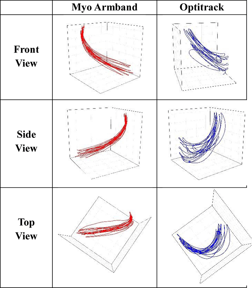
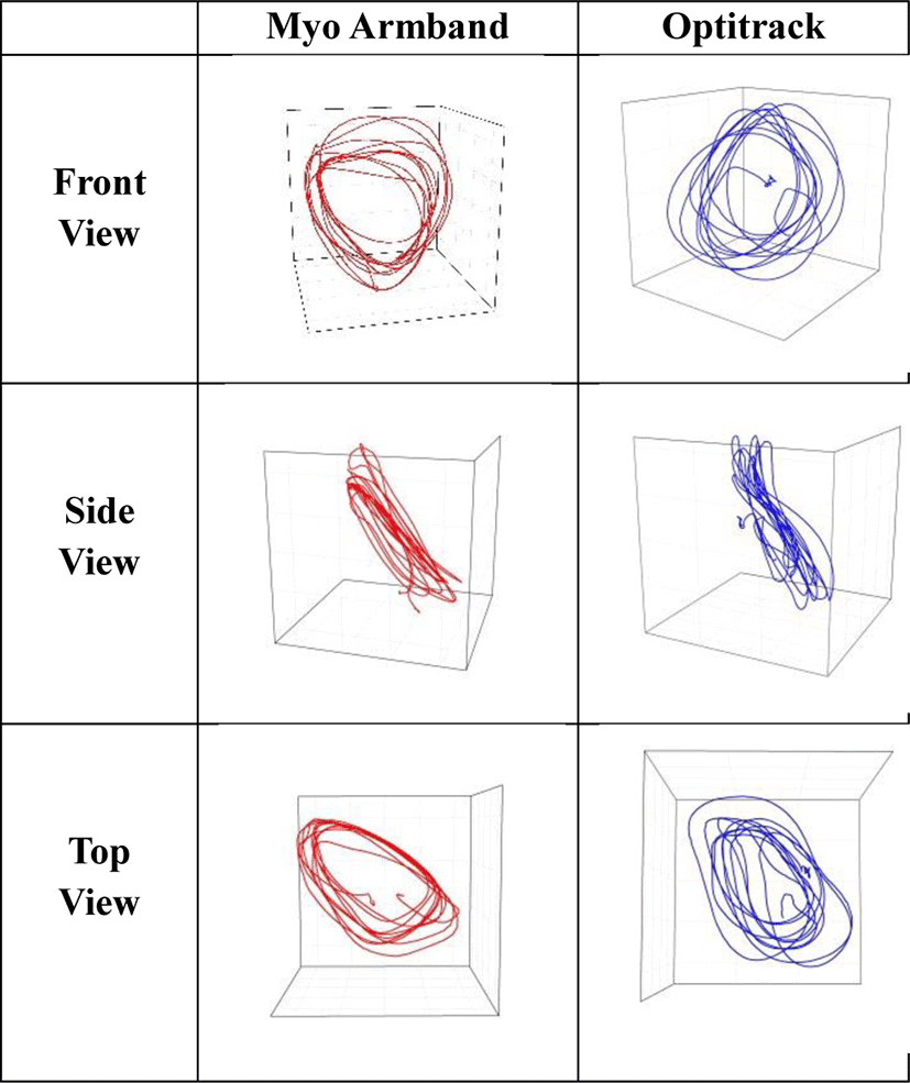
In the human wrist, dart throwing and circumduction gesture provides a more accurate representation of the capabilities of wrist movement [7], [8] because it combines flexion, extension, and radioulnar deviation into a circular motion without simultaneous supination or pronation of the forearm. These coupling of motions are vital in activities of daily living. These activities involve a physiological axis of wrist motion [9], [10] in an oblique plane [11], [12] rather than in the orthogonal flexion-extension or radioulnar deviation axis.
Since we wanted to observe how accurately Myo Armband measures hand-wrist movements, each participant was instructed to make 10 dart throwing motions and 10 circumduction motions. Before each gestures, all participants went through demonstration and was rectified, if needed. Same gestures were done for both Optitrack and Myo Armband.
The use of low cost optical motion capture (OMC) multi-camera systems is spreading in the fields of biomechanics research [13].
Motion capture systems have been used extensively in gait analysis, providing accuracy of within 1% error for 120 mm translations [14]. Motion capture cameras have light emitting diodes that emit light into a capture area. Markers in the capture area reflect the light back to the camera which then determines the size and location of the marker [34]. Using multiple markers and cameras, the motion capture system is then able to triangulate the actual position of markers in 3D space.
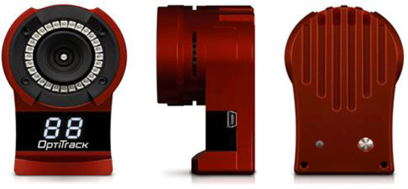
In this experiment, OptiTrack’s Flex 13 (Leyard Company Inc.) was used. This model, Flex 13, has been shown to provide clinically accurate and reliable results in previously studied cases, therefor, was employed. The cameras were of 1.3 Megapixel resolution (1280 x 1024 pixel) and were equipped with stock lenses (5.5 mm focal length, 56° horizontal and 46° vertical field of view). For the gathering and the processing of motion tracking data, Motive from the manufacturer (Tracker v. 1.10.0, NaturalPoint, United States) was used.
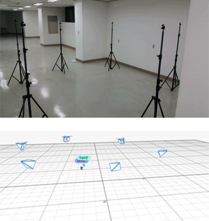
To foreclose any possibility of infrared (IR) interference caused by the sunlight, the experimental setup was employed in a secluded room located at the basement, that of Gil Hospital, Incheon, Korea. Six motion capturing cameras were placed 1.8 meters above the ground, in such a way that they would form a circle of approximately 2.5 meters’ diameter (see Figure 2). The frame rate was set at 120 Hz. The built-in calibration wand CW-500 was used to calibrate the system. its nominal size is 500 mm. The true size of the calibration wand was also measured with an ATOS II Triple Scan MV320 (GOM, Braunschweig, Germany). The wanding process involved moving the calibration wand throughout the entire capture volume. At the end of calibration, the number of samples exceeded 20,000 frames for each camera.
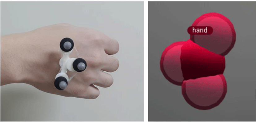
Three retroreflective markers were attached midway between the distal radius at the level of the ridge between the radioscaphoid fossa and the radiolunate fossa [16]. Position and rotation values of the center of the rigid body were exported as XYZ translational coordinates in comma-separated values (csv) format, and later processed by using Microsoft’s Excel (Microsoft, ver. 2013) and Origin Lab (Origin Lab, ver. 8) for the visualization of the hand movements.
As mentioned previously in introduction, Myo Armband is a wearable device that consists of an inertial measurement unit (IMU) and eight electromyographic (EMG) sensors. Multi-accelerometer systems have already shown the ability to recognize activities and detect falls with high accuracy.
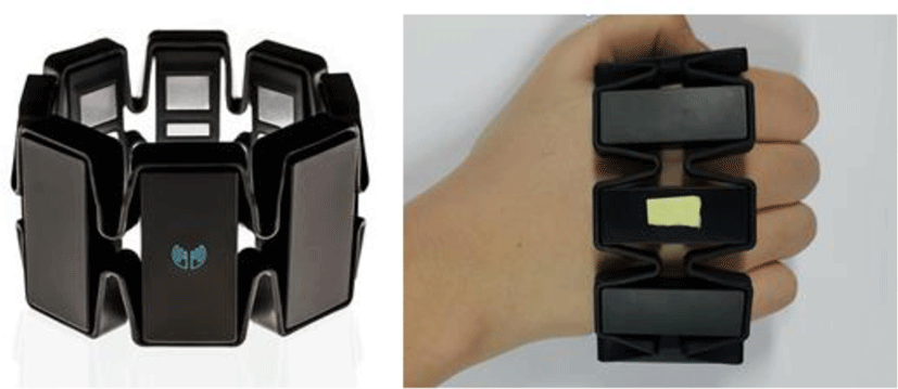
To minimize the errors due to the inconsistency of constant, participants were asked to hold the armband in a way that the accelerometer and gyroscope inside the armband would be placed between the radioscaphoid fossa and the radiolunate fossa. Then, they were asked perform 10 dart throwing and 10 circumduction gesture.
Myo Armband’s data was recorded using a program named ‘Myo Data Capture Windows’, which was written and published by the developers of the Myo Armband, Thalmic Lab. The program detects quaternion data from Myo Armband then transforms it into Euler Angles by following formula:
III. RESULTS
Through this experiment, we were able to visualize and compare hand and arm’s FE and RUD movements measured respectively via Myo Armband and Motion Capture Systems. The movements were captured from three directions: front, side and top. The data captured through Myo Armband is to be compared to data captured with Optic track, which we consider as an ideal value.
IV. LIMITATIONS
In this experiment, there were two obstacles that distracted us from getting ideal results. These are: (1) variabilities in factors such as light reflection, camera setup, and capability of experimental subjects during the motion capturing procedure; and (2) the contraction of arm muscles. Although 3D motion capturing is generally known as a highly-accurate object tracking method, it should be noted that certain conditions are to be met to achieve ideal results. There are various types of 3D motion capturing system, but in this experiment, we adopted ‘optical system’ that makes use of markers coated with retroreflective material. This system requires secluded, ample space with no extra light reflecting object, a plenty number of fixed cameras and proficiency of measurer.
To minimize error, the test was done in a controlled room solely occupied by measurer at the Hospital room in the basement. The cameras were set up in a circular shape with a circumference of about 2 meters so that the trajectory of retroreflective markers could be captured from all directions.
Despite these efforts, there were few frames in which one or more markers were not recognized. Synthetic frames were supplemented by the program Motive’s built in function. Although errors stemming from the missing frames do not significantly affect the overall results, it may still be reduced by averaging over the numbers from motion capturing cameras during the test procedure.
Another factor that may affect the test results is the repeatedly contracting muscles of the subject’s arm. Since the test procedure involves drastic movements of arm, markers are susceptible to displacements along with the contracting skin, therefore reducing accuracy of the test. To reduce the resulting errors, we created a sculpture using 3D-Printing, where we attached the markers so there won’t be direct contact between the skin and the markers.
V. CONCLUSION
The incorporation of elements including accelerometer, gyroscope, and electromyographic (EMG) sensors makes Myo Armband a versatile device deployable in a range of applications. Starting from simply as a substitute for computer mouse, it may also be used as a maneuvering device for game or as a drone controller. The wireless data communication through Bluetooth is also a huge advantage, since it grants users spatial freedom.
Myo Armband’s accuracy has been directly and indirectly verified in several studies. For instance, researchers at Johns Hopkins University is now inventing a mind controlled robotic arm that can touch and feel, and they are using two Myo Armbands to measure the electromyograph (EMG) of muscles to see the corelationship between EMG and brainwaves [17]. Considering the level of accuracy required in this kind of experiment, the researchers’ selection for Myo Armband testifies its performance.
In another study, Myo Armband was used to collect the body signals of people suffering from Parkison’s syndrome [18]. Parkison’s syndrome is a disease caused by the loss of nerve cells in specific parts of the brain. They put Myo Armband on patients’ body to record and analyze the EMG data.
The company ADORA used Myo Armband as an assist device during surgery. During medical operation procedures, the range of surgeon’s arm movement is rather limited, so the assistance of staff members is needed. Myo Armband, if worn inside the operating gown, may be used as a control device for medical equipment.
Previously employed sensors were expensive, and required a lot of curation efforts to achieve an acceptable level of data accuracy. Myo Armband, with its fair price and decent performance, is expected to find increased uses in various fields of science, especially in medical engineering.