I. INTRODUCTION
Video conferencing is an interactive system for telecommunication which allows users from different locations to communicate through simultaneous two-way video transmission. In these days, as telecommunication technologies have grown up, many consumers use free video conferencing software in their homes using their laptops and webcams.
However, most video conferencing systems lose the eye contact due to improper locations of cameras. The lack of eye contact may cause unnatural and unpleasant communication situations. Thus, the eye contact problem is the primary hindrance in video conferencing systems. Over the past decade, various methods for eye gaze correction have been proposed. However, some of them require complex hardware configurations and expensive system setup [1~6].
In this paper, we propose a simple eye gaze correction method using the three-dimensional (3D) affine transformation to correct the eye gaze problem. We employ the depth image-based rendering (DIBR) technique to generate virtual views using the captured color and depth data [2]. In particular, we apply DIBR for eye gaze correction in home video conferencing systems using Kinect v2. A simple, low-cost hardware setup is a strong point of the proposed method.
The remainder of this paper is organized as follows. In Section 2, we briefly explain two existing DIBR methods for eye gaze correction. In Section 3, our proposed method is explained in detail. After we analyze experiment results in Section 4, we conclude this paper in Section 5.
II. RELATED WORK
There are two existing DIBR methods for eye gaze correction. Ho and Jang proposed a method to use stereo cameras and one Microsoft Kinect camera [3]. The depth map acquired from the Kinect camera was projected to stereo camera positions using 3D image warping. They performed the camera calibration to estimate camera parameters of the stereo camera set and the depth sensor of the Kinect camera. Since the distance from the stereo camera set to the object is not the same as the depth from the depth sensor of the Kinect camera to the object, they calculated the Euclidean distance between the world coordinate and the center point of the stereo camera set. Then, they performed the joint bilateral up-sampling (JBU) operation to fill empty regions caused by depth data of low resolution. Since the warped and up-sampled Kinect depth map has occlusion areas and inaccurate depth values, they employed a global stereo matching method to obtain the accurate depth information. In their method, the Kinect depth information is included as additional evidence of the global energy function. Then, they calculate the camera parameters of gaze-corrected position by adjusting the rotation and translation matrices of the two views using Euler angles. Finally, the left image is mainly used to generate a gaze-corrected image, and the right image is used to fill empty holes for the synthesized image.
Kuster et. al. [6] proposed a simple gaze correction system for home video conferencing using the Kinect camera. They transferred only the face seamlessly into the original image to preserve both the integrity of the background and foreground. Thus, they tracked facial feature points along the chin, nose, eyes, and eyebrows. Then, they computed an optimal stencil to cut the face. The optimal stencil ensures not only spatial consistency of the image, but also the temporal coherence of the sequence in video conferencing. When transforming the face, they used rigid transformation which preserves distances between all pair of pixels.
Unlike the previous works, we propose a simple method that does not require any camera parameters. Ho and Jang’s method [3] has high time complexity due to the global stereo matching operation and its performance depends on the quality of the depth information; however, our method transforms only the face using the 3D affine transformation. Although we need to apply the image in-painting operation, we can generate eye gaze corrected results. In addition, we can obtain improved images of high resolution by performing the depth up-sampling operation.
III. PROPOSED METHOD
The proposed method requires a short initial step only once. After we detect the user’s facial feature points to create a face mask that represents the area for eye gaze correction. We use the high-definition face feature detector that is supported by Kinect v2. The face feature detector tracks 1347 facial feature points in the 3D space. Then, we apply the 3D affine transformation to extract 10 facial feature points along the user’s forehead, eyes, cheekbone and chin when the user is looking at the display monitor and the color camera of Kinect v2, respectively. The 3D affine transformation matrix is estimated using 10 matching points, as described in Eq. (1).
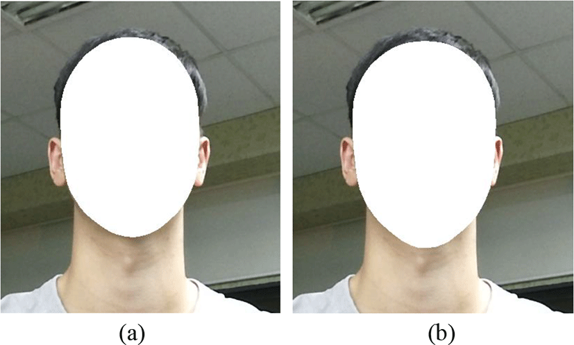
Since our proposed method transforms the human face using the 3D affine transformation, the quality of eye gaze corrected images depends on the precision of the face mask. In the proposed method, we convert all facial feature points to color space points. Then, we have several overlapped vertex points in the 7890 vertex data. Finally, we draw 2630 filled triangles with 255 values on the new image using each three vertex data. They filled all triangles in the face mask that represents the user’s face area in detail.
Before we apply the affine transformation, we need to correct the radial distortion and up-sample the depth image to the same resolution as the corresponding color image. However, we have three choices to up-sample the depth image: 1) If the user is not wearing glasses, we use the mapping color frame to the depth space. 2) If the user is wearing glasses, we use the mapping depth point to the color space. Then, we fill the empty area using the joint bilateral up-sampling (JBU). 3) Instead of JBU, we use the mapping color frame to the depth space. Then, we perform the depth image in-painting to correct the reflection error.

For eye gaze correction, we perform the 3D affine transformation. Once we acquire a color space point that is one of the pixels on the face mask, we convert the color space point to the camera space point and conduct matrix multiplication with the affine transformation matrix. We use Eq. (2) to convert the luminance value of the camera space point, respectively.
We can easily convert the camera space to the color space using Kinect v2 SDK. Since we used Eq. (2) when converting the color space to the camera space, we acquire eye gaze corrected results using Eq. (3).
We can create the in-painting mask to perform image in-painting. The in-painting mask has to be accurate to refer to neighboring pixels which are not holes. Thus, we generate an accurate in-painting mask using face feature points.
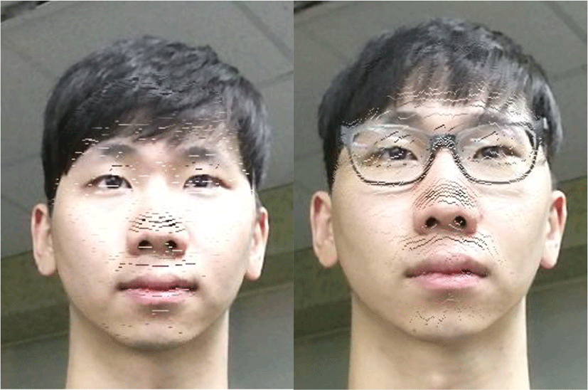
We transform all face feature points using the 3D affine transformation matrix to create the corrected face mask. As a result, some round-off errors except in thick spaces on object boundaries remain 255 value pixels on the corrected face mask image. A set of the remained 255 value pixels is the in-painting mask. Most round-off error holes in the result of eye gaze correction are matched 255 value pixels in the result of the in-painting mask.
However, there are thick spaces which comprised of 255 value pixels in the result of the in-painting mask. The thick areas occur in the image in-painting mask due to neighbor pixels. Thus, we have to update the in-painting mask by removing those thick fields. To remove the thick areas in the in-painting mask, we perform the connected-component labeling algorithm to gather neighboring holes. To separate the thick fields from small holes, we use the 4-connected method in the connected component labeling algorithm [7].
When restoring lost areas in the image, we can use the Telea image in-painting algorithm [8]. On the other hand, many single pixel sized holes are present in the result of our proposed method. In this case, taking the existing pixel value from the original color image is more efficient than generating a new pixel value by referring to neighboring pixels. Thus, we use the original y coordinate image when performing the eye gaze correction. In addition, we put a reference direction between the upper and lower limits in the y coordinate image according to the remaining decimal value after 3D affine transformation.
IV. EXPERIMENTAL RESULTS
We have designed a system for eye gaze correction. We use a 27-inch display monitor and set the Kinect v2 below the monitor. Then, we align the color camera of Kinect v2 at the center of the monitor. In addition, we raise an angle of Kinect v2 to cover the user’s face for eye gaze correction. The distance between the Kinect v2 and the user ranges from 800 mm to 1200 mm. Meanwhile, the gaze-corrected distance between the Kinect v2 and the center of the monitor is between 2000 mm and 2500 mm.
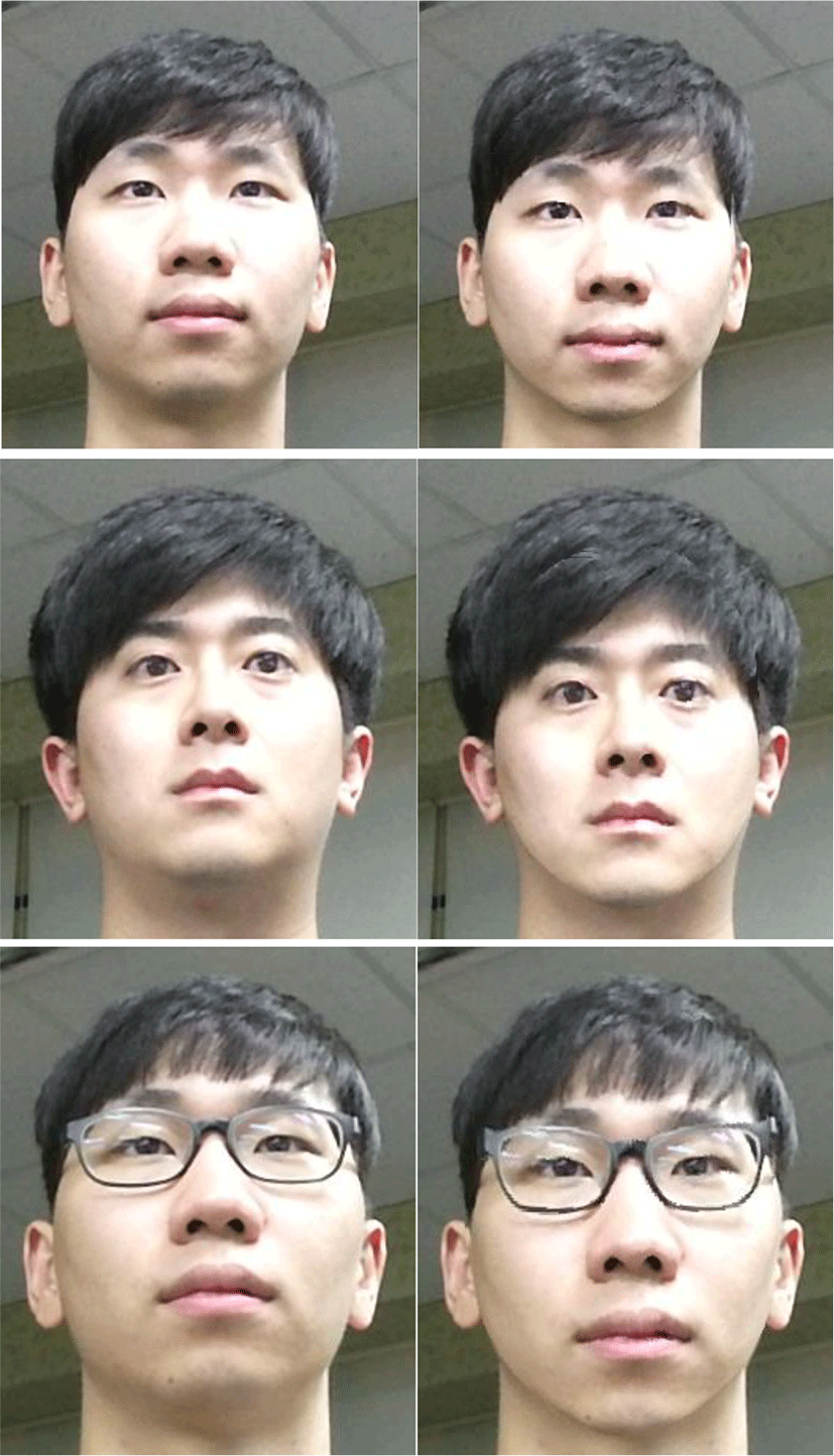
The color camera and the depth sensor of Kinect v2 capture images at the resolution of 1920×1080 pixels and 512×424 pixels, respectively. Then, we use different depth up-sampling methods depending on whether the user is wearing glasses on. As a result, we have obtained eye gaze corrected results at about two frames per second on the consumer computer, as shown in Fig. 3.

V. CONCLUSION
In this paper, we proposed a simple method for eye gaze correction using the depth image-based rendering technique. The proposed method allows us a low-cost system setup using Kinect v2. In addition, we can obtain high resolution images by performing the depth up-sampling operation. Even in the case of wearing glasses, we can produce good results by refining depth errors due to the reflection.
