I. INTRODUCTION
According to traffic accident statistics of highway traffic in the last 10 years, the traffic accidents caused by drowsiness have been higher than the traffic accidents caused by over speeding. The number of traffic accidents may be reduced significantly if actions to try to wake up driver’s sleeping is taken through detecting drowsiness during driving. Several methods to detect drowsiness during driving have been studied. Among the methods for detecting drowsiness, there is a method of continuously observing the driver’s condition by utilizing biological signals such as EDA, HRV, ECG, and EOG [1]. The method of eye detection through corneal reflex of pupil using two lights, an on-axis light and an off-axis light, to detect drowsiness is studied [2]. These methods detect drowsiness accurately, but they are needed to install the additional devices. Methods of detecting drowsiness through the color image analysis without the installation of these additional devices have been studied as follows: the method of extracting facial feature points using regression tree ensemble algorithm to detect yawning, eyes, and a direction of head[3]; the method of determining the drowsiness by the frequency of eye blinking and the duration of eye closure[4]; the method for detecting the region that the sum of absolute difference(SAD) of the reference image is more than a threshold[5]; the method for determination of the eye closing when the number of black pixels is below the threshold[6]; the method of determining the drowsiness by measuring the time when the black area of the eye area extracted using the Haar-like Feature[7]. However, the conventional methods depended on the color picture has disadvantages that the accuracy of the face detection is reduced when the face is on the side. In addition, these methods little detect the face in a dark environment such as a nighttime. This is the fatal disadvantage because drowsiness during driving occurs mainly at night.
The infrared or depth picture can be used instead of color picture in detection of face and eyes. The infrared and depth pictures have the advantage that the change of pixel is less in change of illumination compared to color image.
In this paper, the infrared and depth pictures are used to detect the face and eyes. The face of a driver is detected by using the depth picture. After that, eyes in the detected face is found by using the infrared picture. In the eyes detection, the eyes are found by Haar-like features.
II. Detection Method of Drowsiness during driving
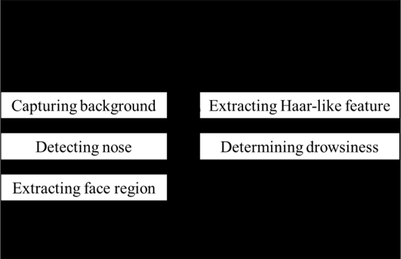
In this paper, we detect the drowsiness during driving by using both the infrared and depth pictures. First, we detect the face by using the depth picture. After that, we detect the drowsiness by extracting Haar-like feature. The flowchart of the proposed method is shown in Fig. 1.
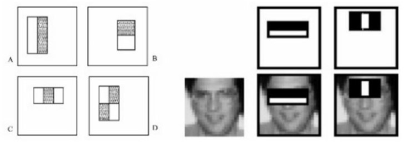
Regions used in the Haar-like features are defined by rectangles that have various patterns consisting of in the light and dark areas as shown in Fig. 2. Haar-like method finds the meaningful features based on differences in pixel values in each region. To extract the features, the Haar cascade method is used. Haar cascade method subtracts the brightness value corresponding to the black part and the white part in the image, and finds out the threshold value. Since the addition and subtraction of brightness values are inefficient, the integral image method is used.
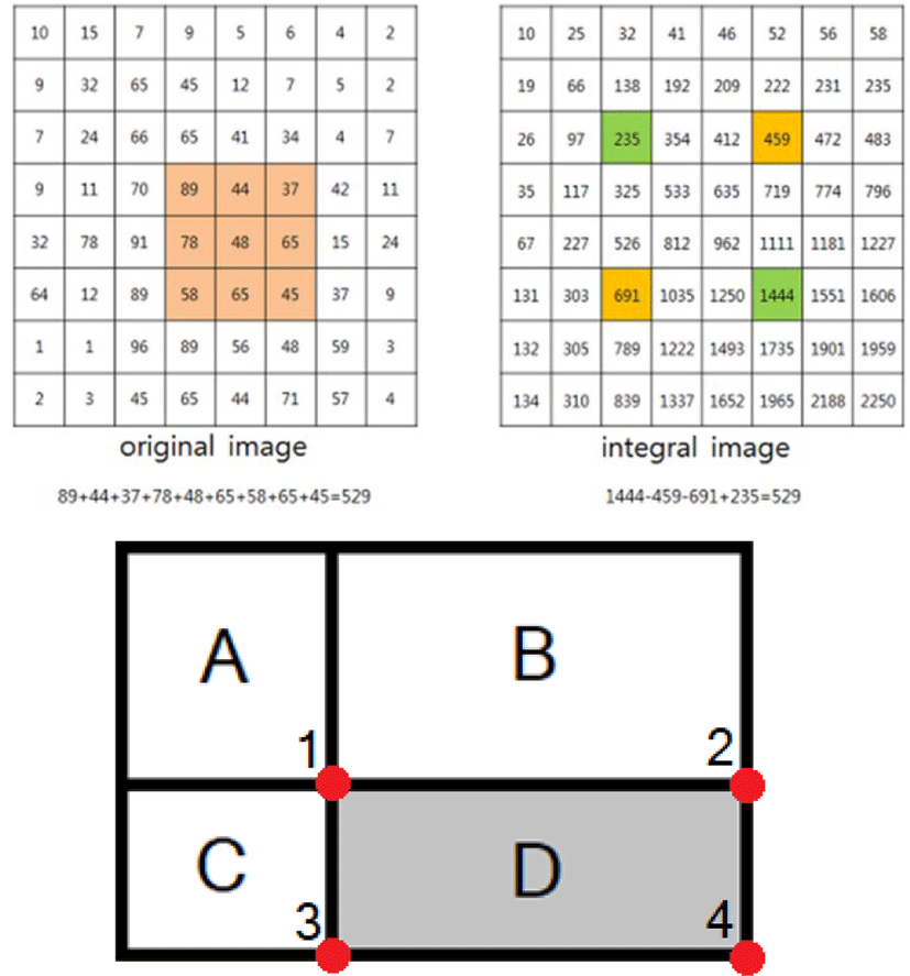
The integral image method starts from the (0, 0) point of each pixel in the original image in Fig. 3, and continuously accumulates the pixel value. The pixel is moved to the next pixel to generate an integral image. If the Haar cascade method is only used, the pixel value in D must be added to obtain the sum of the brightness of D. However, if the sum of brightness of D is obtained by using the integral image, the sum of brightness of D is calculated by the sum of brightness in 1, 2, 3, and 4 in Fig. 3. Therefore, if the sum of the brightness of the rectangle from the origin to each pixel is stored as the integral image, the sum of pixel brightness values of a specific region can be obtained by adding and subtracting the brightness value of each region.
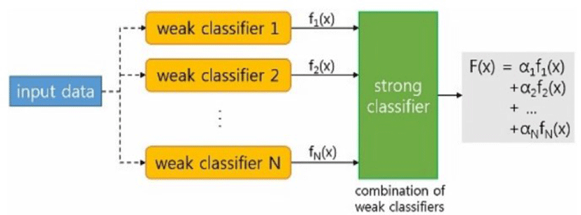
The next step is AdaBoost, which is the combination of ‘Adaptive’ and ‘Boosting’. AdaBoost is a way to amplify the performance of the final strong classifier by learning step by step supplementing simple weak classifiers complemented as shown in Fig. 4. In the boosting process, we combine weak classifiers with low prediction performance to generate one strong classifier with better performance. In the adaptive procedure, when the weak classifiers are sequentially learned one at a time, the information obtained by misclassifying the learned classifiers is reflected in the learning of the next classifier to compensate for the disadvantages of the previous classifiers. The user can focus on the data that is misclassified and learn and classify the data. The final strong classifier can be obtained by applying weights to each weak classifier and combining them.
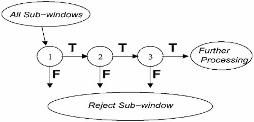
After the Adaboost process, we use the cascade process to detect the object by sliding the boosted strong classifier on the input image. This maintains the characteristics of the object, slides a simple strong classifier first, and slides a stronger classifier with a slightly stronger probability of not being an object when passing through. In this case, if we fail to pass, we will skip the non-object part in such a way that the part will be skipped during the next sliding, finding the final result. As the cascade method progresses, the area used for detection becomes smaller, so the amount of computation decreases and the speed increases.
First, the background image is taken to separate the driver object from the depth image. In the background image which is photographed later, the reference background is subjected to the arithmetic operation, labeling, and morphological operation to extract the object and remove the noise. If the drowsiness is detected through the depth image. Even if the passengers other than the driver who is in the car are photographed at the same time, since the infrared ray and the depth sensor are located closest to the driver, the driver is generally the largest object. It is possible to label the driver as the largest object without disturbing the user.
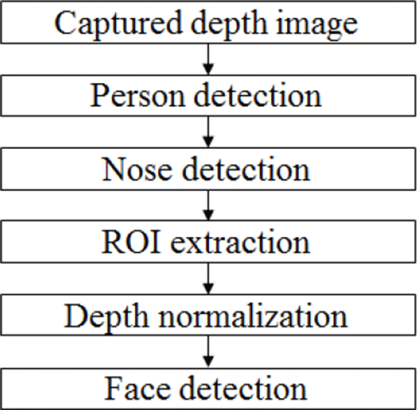
To detect the driver’s face, the driver’s body is captured by the depth camera. In order to extract the driver from the captured picture, we obtain the background by the depth camera. Background and foreground are separated by obtained background picture.
The nose is generally located at the closest distance to the depth camera, and the position of the nose becomes the pixel with the minimum depth value. The neighboring pixel feature and the facial structural feature are utilized in order to prevent the jaw, hand, chest, etc. other than the nose end point from being mistaken.
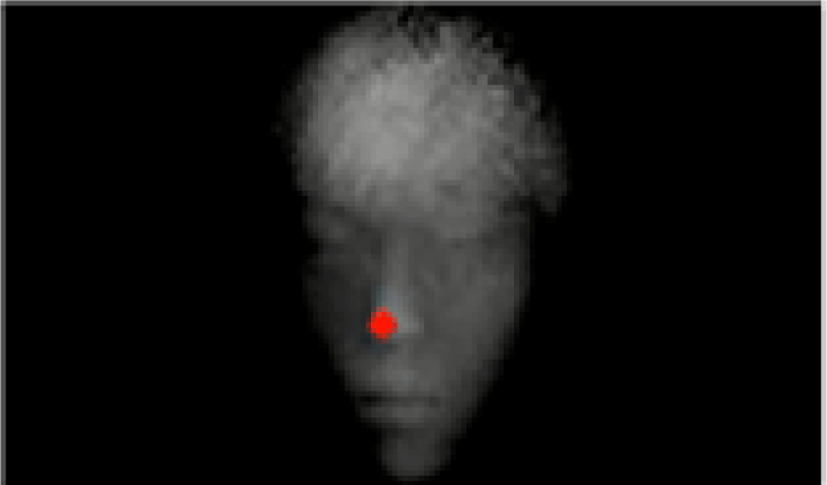
The feature of the adjacent pixel is that the depth value of the upper and lower right and left pixels of the nose end point, the depth value of the lower jaw and the depth value of the jaw are larger. The face structural feature is that the nose end point is located at the center of the face, the background area and the width of a common human face. In order to detect the position of the eye in the extracted driver object, a pixel corresponding to the nose end point is searched, and the eye region is detected by cropping the pixel corresponding to the nose end point by a predetermined magnitude. In order to find the end point of the nose, the binarization is performed and the search is performed in the horizontal direction. Then, the N consecutive pixels from the left to the right with respect to the Pi pixel are searched for pixels having a depth value larger than that of the immediately preceding pixel by equation (1).
where, i is the position of current pixel and N is the range of finding pixels.
This is applied to both vertical and horizontal pixels, and a pixel satisfying both of them is used as a candidate pixel. Thereafter, eight neighboring points separated from Pi by a predetermined number of pixels are compared with respect to the candidate pixels, and it is checked whether the compared pixels have a greater depth value than the candidate pixel Pi. This is based on the fact that the nose around the face is more protruded than the other areas. Then, the coordinates of the fixed region based on the coordinates of the nose of the depth image obtained by depth acquisition are assigned to the infrared image and the region is designated as the region of interest as shown in Fig. 8[9].
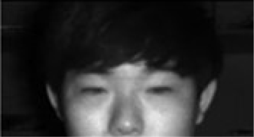
In order to detect the eyes of the driver in the extracted eye region of Fig. 9, Haar-like feature is applied and two different cascades are applied to improve the accuracy.
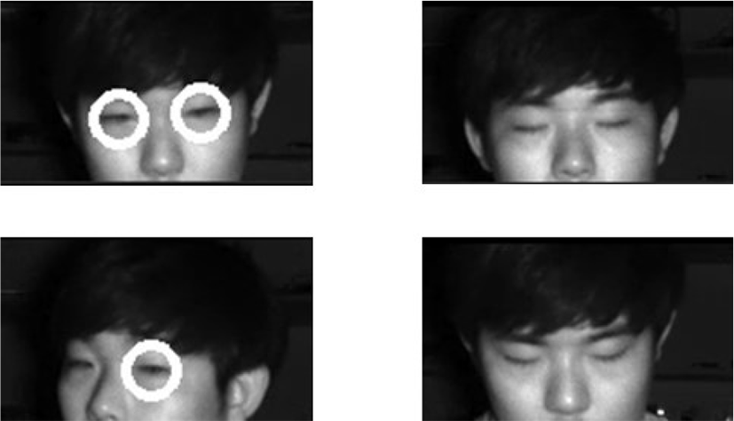
From the features of the eyes, the drowsiness state is found as follows [8]. In normal state, the fast and sharp flicker can be found. At the beginning of drowsiness, long flicker is repeatedly found. In drowsiness, closed eyes is found continuously. The each eyes are detected through the Haar-like feature, the eye can be detected even if the driver turns the direction of the head to the side. Drivers at early and drowsy states can often determine whether or not they are drowsy in the eye. Therefore, if the eyes are not detected for about 2 seconds when the face of the driver is normally detected, it is determined that the driver is in a drowsy state and the driver is warned of drowsy driving.
III. Simulation Result
In order to measure the accuracy of the proposed drowsiness detection, we use Kinect v2 as capturing the depth picture and the infrared picture. The specification of device for simulation is shown in Table 1.
| Color | Resolution | 1920×1080 |
| FPS | 30 | |
| Depth | Resolution | 512×424 |
| FPS | 30 | |
| Depth acquisition range | 0.5 ~ 8.0m | |
| Person detection range | 0.5 ~ 4.5m | |
| Degree | Horizontal | 70 degrees |
| Vertical | 60 degrees | |
In the bright environment and the dark environment, depth images of the front and side of the person are taken for 30 seconds for each measurement, and the total frames and the frames in which the eyes were detected were measured. Table 2 shows the accuracy measurement results. In this result, the face is detected with the accuracy of 88.3% in the bright environment and is detected with the accuracy of 90.8% in the dark environment.
Table 3 shows the accuracy of the drowsiness detection. We determine that it is the drowsiness state when eyes are kept closed for more than 1500ms in consideration of temporary blinking of eyes. In this simulation, the drowsiness detection accuracy is more than 99% irrespective of the illumination environment.
| Brightness of illumination | Total frames | Detection Frames | Accuracy of drowsiness detection |
|---|---|---|---|
| Bright | 1356 | 1354 | 99.86% |
| Dark | 1454 | 1444 | 99.32% |
| Total | 2810 | 2798 | 99.57% |
IV. Conclusion
In this paper, we propose the method of the drowsiness detection by using the depth and infrared pictures. The proposed method uses the depth picture to detect the face and obtain the region of the detected face. After that, the obtained region is assigned to the infrared picture. The assigned region in the infrared picture becomes an input of the extracting Haar-like features. The eyes are detected by Haar-like features of the face. If the eye is not detected for a certain time while the face is detected, the method determines the face as a drowsy state. This method solves the problem that eyes are not detected in the dark environment. By detecting the drowsiness in dark environment through the proposed method, it is expected that the number of traffic accident caused by drowsiness is reduced significantly.