I. INTRODUCTION
Realistic visual effects made using three-dimensional (3D) computer graphic technologies play an important role in increasing the realism of films and animations. In the age of digital images, CG is highly recognized and even used as a measure of a country's technological prowess [1]. Traditional special effect generation methods have mostly been replaced with visual effects technologies [2] and the domain of which visual effects can be produced by computers has expanded [3]. Cutting-edge digital visual effects production technologies increase viewers’ preference for films made using them [4].
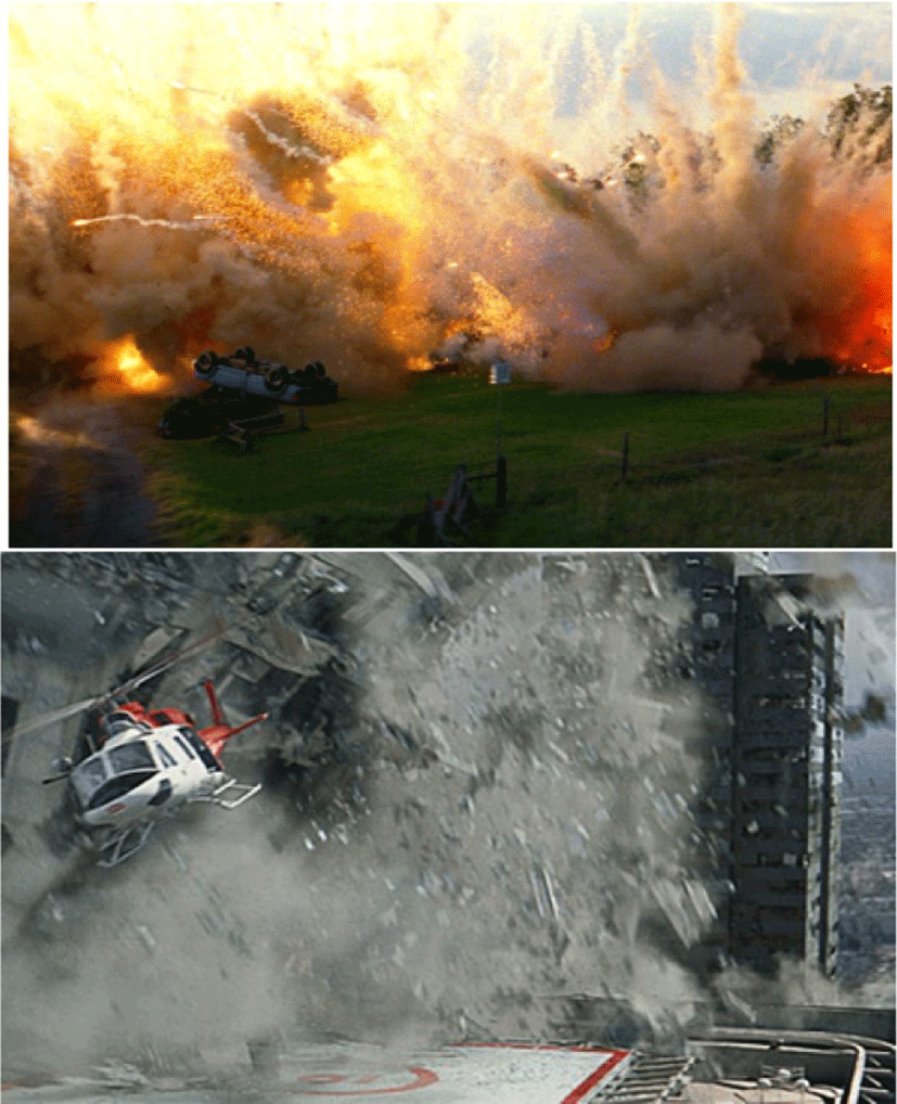
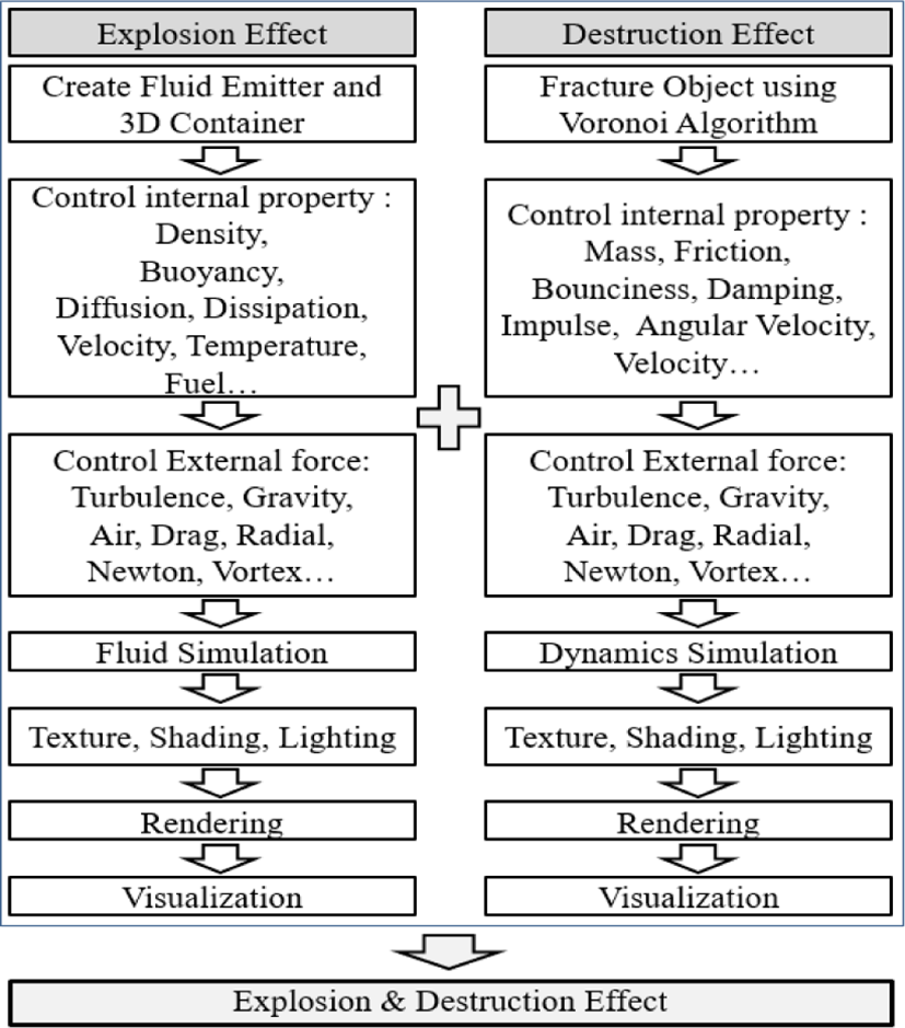
According to CG visual production based on computer graphics development, all visual images can be expressed. [5]. The explosion and destruction of architectural structures in various scenes are some of the most frequently used visual effects. However, they are difficult to generate using computers and require significant technical abilities. As such, it can be difficult to make high-quality effects. Furthermore, equations and many parameter values are limited, so they are difficult to produce and take a long time to generate [6]. In the real world, explosions and destruction are naturally connected. However, these effects are produced separately and in different ways by 3D computer graphic technologies. Explosion effects are generated through fluid simulations in Fig. 1(a), and, destruction effects are created by simulating dynamics in Fig. 1(b).
Explosions and destruction are created through different processes and so require a final process to combine them to make them look a unified, natural effect. This final process requires a high level of technical skill and expertise. The present study was conducted to test a new production process as a way of solution that is less time-consuming than existing processes that require producers to conducted through the repeated simulations.
Computer-generated explosion and destruction effects are generated based on physical and chemical laws of nature. Explosions in the real world generate a large amount of heat and kinetic energy that affects the surrounding architectural structures and ground, causing some objects to crack and ultimately be destroyed. An accurate understanding of how this phenomenon occurs results in more realistic computer-generated visual effects [7]. In order to create realistic and high-quality effects, tremendous amount of capital, manpower, time, and technology is required. However, actual production often takes place within limited resources, so developing an efficient production method within limited resources is the most direct way to improve the completeness of the work [8]. The purpose of this study is to experiment with pipelines that embody explosion and destructional visual effects within limited capital, manpower and time.
This study was conducted to test a method for generating both explosion and destruction effects simultaneously that is based on motion and the principle of the conservation of energy. The experiments were conducted by simulating the conversion of heat energy created by an explosion into kinetic energy that generates destruction to produce more realistic destruction effects.
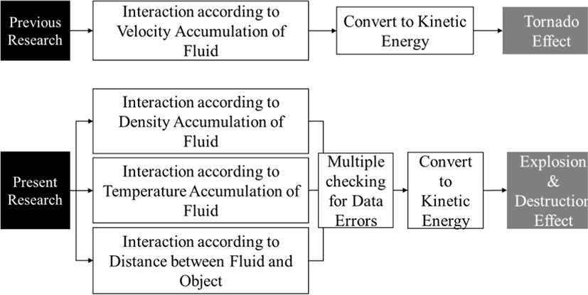
This research is follow-up research of “A Study on Energy Transfer and Conversion in 3D Visual Effects” [9] published in the ‘Korean Society of Cartoon and Animation Studies’ in 2021, the basic concept of energy transfer and conversion in computer graphics presented in previous research was expanded, and experimental research was further subdivided and developed. In previous research, experiments were conducted centered on the Tornado effect through the relationship between fluid velocity and particle motion. However, experiments were conducted centered on the Explosion & Destruction effect through the density and temperature of fluid, and distance between particles in this research. In order to create a more realistic visual effects through effective interlocking of fluids and particles, the one experimental stage was expanded and developed into three stages. This research has great value as a follow-up research in that it minimizes the occurrence of errors and implements an efficient solution based on accurate data extracted through three sequential experimental process.
II. LITERATURE REVIEW AND RESEARCH METHODS
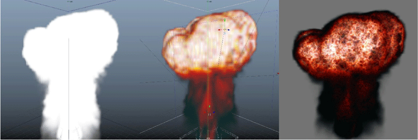
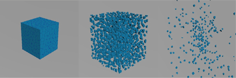
In the real world, explosions cause, but when generated as visual effects, they must be created separately and then later combined. Explosion effects are produced through fluid simulations while destruction effects are produced through dynamics simulations. Explosion effects are produced through fluid simulations because they can more realistically replicate natural phenomena, such as the movement of water, fire, and smoke [10]. Fluid simulations first require the production of a 3D container that creates and controls the fluid. It simulates the realistic movement of the fluid according to its properties and the application of simulated force. The fluid’s simulation characteristics are density, buoyancy, diffusion, dissipation, velocity, temperature, and fuel. The simulated forces include turbulence, gravity, air, drag, and vortices in the 3D graphic environment. After creating the desired motion through repeated simulations, realistic colors, textures, and lighting are applied. The final effect is produced through rendering. The explosion effect production process is shown in Fig. 3. Destruction effects are generated by first cracking an object into pieces and separating them. The fragments are broken realistically simulating the physical properties of each piece. Then external forces are applied to each piece. Voronoi diagrams are used to crack the object into pieces.
Voronoi diagrams allow for finitely many points to be simulated on a given plane based on given point data so that each partitioned cell includes only one point. Then an algorithm calculates the closest distance [11]. In Voronoi diagrams, objects are partitioned according to each of the given points and then physical collisions are simulated to produce the destruction effect [12]. Object properties include mass, friction, bounciness, damping, impulse, velocity, and angular velocity. As with fluids, the forces that are applied to objects include turbulence, gravity, air, drag, and vortices. The destruction effect production process is shown in Fig. 4.
Explosion and destruction effects are produced through repeated simulations until a sufficiently high-quality effect is produced. Then they are combined to make it look like they are naturally interlinked. The combined explosion and destruction effect production process is shown in Fig. 5.
Although the demand for realistic visual effects is high, there is an insufficient amount of experimental research and literature regarding this topic. This is because the field of visual effects is a practical study field with the purpose of visualization, and as such, most related researchers are devoted in the industry and focused on production of work, which has led to the low level of scholarly achievement for the purposes of pure research. Due to this insufficiency in research, there are not enough materials that can be used as references by a creator who is not as skilled in the process of learning the techniques. As such, the time consumed in the process of producing a successful outcome is very high.
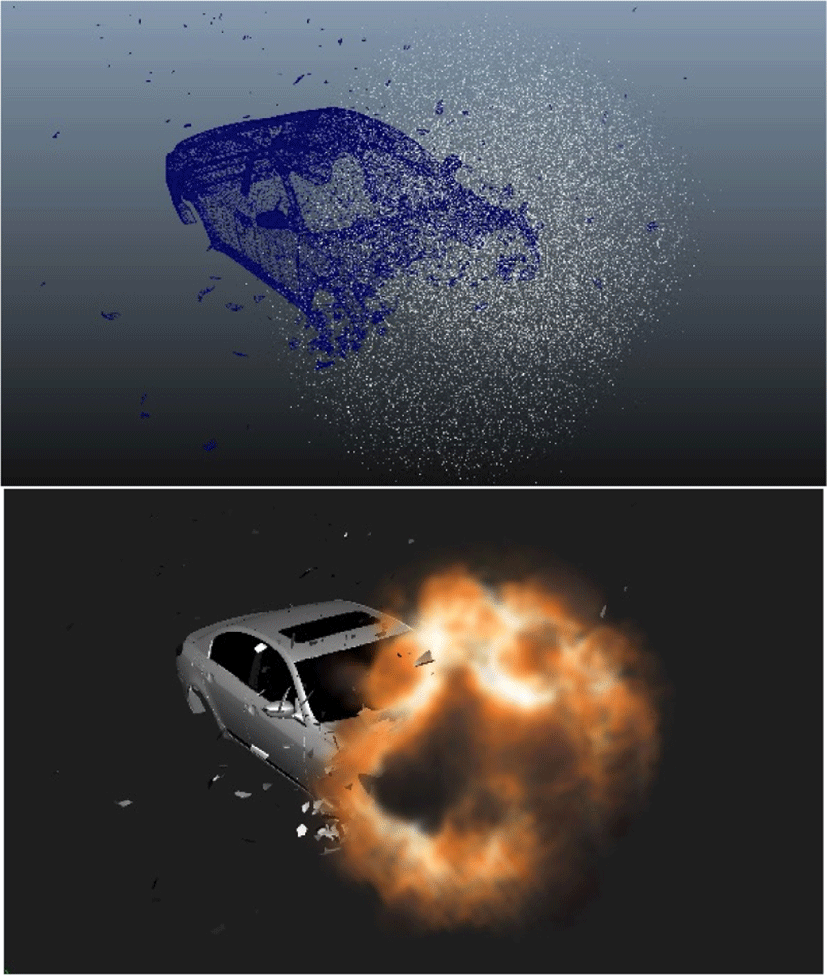
The experiments in this study were conducted to examine the effectiveness of a proposed process that links the creation of destruction and explosion effects using fluid simulations. Existing processes simulate explosion and destruction effects separately and then combine them so that they look like they are interlinked. However, this study was conducted to test a method for actually interlinking them during the production process. The experiments produced a visual effect in which the surface of a vehicle is destroyed due to an explosion, the initial vehicle body is completely shattered, and a different vehicle body is left.
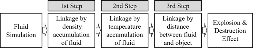
Three experiments were conducted that examined how the effects could be interrelated by fluid density, fluid temperature, and how far fluid was from relevant objects. The experimental process is shown in Fig. 6. Three experiments were conducted separately to independently manipulate various variables to produce objective and clear results. The experiments were conducted using Maya (Autodesk, Seoul, South Korea). Fluids in completed simulations were interlinked with destruction effects in the experiments.
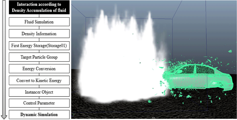
Density is the mass in a given volume. Density in 3D computer graphic fluid simulations is determined by the total amount of fluid inside the 3D container space and it is one of the fluid’s basic properties. Fluid diffusion and velocity are the core factors that affect fluid motion and they can change fluid density in a certain unit of volume. However, the total mass within a fluid 3D container does not change, so neither does total density. The objects in the experiment were partitioned using a Voronoi diagram. The pieces were converted into dynamic objects in order to simulate the effects of kinetic energy. Maya can convert static objects into dynamics objects that move based on their properties and forces that act on them.
Dynamic objects are called instancers and particles are inserted at their centroid point. Instancer maps correlate particles with their corresponding objects and those objects respond to commands sent to their corresponding particles [13]. Particles can receive input values, which enable the simulation to proceed dynamically [14]. In this experiment, particles were commanded to enter the first energy storage (Storage01) in order to increase the density of fluid where moving fluid and particles come into contact. This was designated as a separate parameter.
When the preset explosion effect simulation was conducted, the fluid approached and came into contact with the target particle group, which were the particles in the instancers, through diffusion and motion. After initial contact, the density of X is stored in Storage01 for each target particle group. When the density reaches the preset threshold, stored energy is converted into kinetic energy, causing the particles to move. Unlike fluids, rigid body motion requires a center of rotation, radius of rotation, and rotation angle.
The converted kinetic energy information is transmitted to the particles’ velocity and angular velocity properties, causing them to translate and rotate. The experimental procedure and results are shown in Fig. 7. The command applied to the target particle group was transmitted to the objects through particles, causing the destruction effect of a fragmented object to be naturally interlinked according to the fluid density accumulation (Fig. 7).
Experiment 1 tested how the explosion and destruction effects could be interlinked by fluid density. The value in Storage01 for each particle was converted to kinetic energy, causing the destruction effect to occur when the value reached a threshold. However, fluid naturally dissipates over time, so in Experiment 1, too much fluid dissipated, leading to insufficient energy being stored. As such, some of the objects did not move. Therefore, in Experiment 2, the explosion and destruction effects were interlinked according to fluid temperature to overcome this limitation.
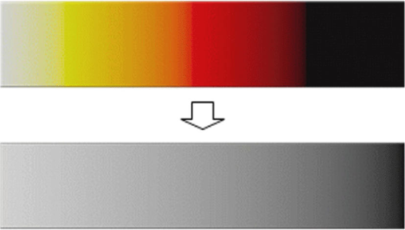
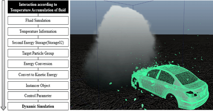
In real explosions, the rapid emission of energy from the center of an explosion causes violent fluid motion. The high temperature created by the explosion decreases over time. Temperature change is reflected in 3D computer-generated explosion effects by fluid color. The colors from hottest to coldest are white, yellow, orange, red, and black. Thus, the center of an explosion would be white because the temperature is the highest and as diffusion occurs, the color changes to yellow, then orange, then red, and then black when combustion is completed, at which point there is typically a lot of smoke.
The fluid colors have to be normalized before a simulation is conducted. In explosions simulated using fluids, the highest temperature at the moment of the explosion is expressed as white while the lowest temperature at the completion of combustion is expressed as black. Thus, the fluid changes colors between white and black. Normalized data can be expressed by using 1 as the maximum value and 0 as the minimum value in Fig. 8.
An explosion effect simulation was conducted using the color spectrum to represent temperature. Each particle was given a second energy storage property (Storage02) that reflected its temperature with values between 0 and 1 from the moment that the fluid and the particle come into contact.
The temperature data of the fluid from the moment that it meets the target particle group is stored in Storage 02. Objects move when their temperatures reach a temperature threshold. Particles’ temperature values were used to calculate their velocities and angular velocities properties as in Experiment 1 and their translation and rotation were also simulated. The process and its results are shown in Fig. 9. Motion was successfully simulated through energy conversion, overcoming the limitations observed in Experiment 1.
Experiments 1 and 2 tested the effect of interlinking explosion and destruction effects by fluid density and temperature, respectively. They showed that parts of the target particle group’s motion were unnatural. Of the external forces exerted upon the fluid, turbulence caused irregularities in the fluid’s motion in order to create natural fluid motion. The irregular fluid motion caused by turbulence influenced fluid density at particular points in the 3D container. A 3D container is a virtual space composed of voxels, which contain 3D spatial information. In Experiment 2, color information was also added to the voxels. Turbulence was exerted on the fluid, causing it to have irregular motion and, in turn, causing it to not remain only in particular voxels. In other words, turbulence disturbed the accumulation of density and temperature. Experiment 3 was conducted to test a method of resolving this problem.
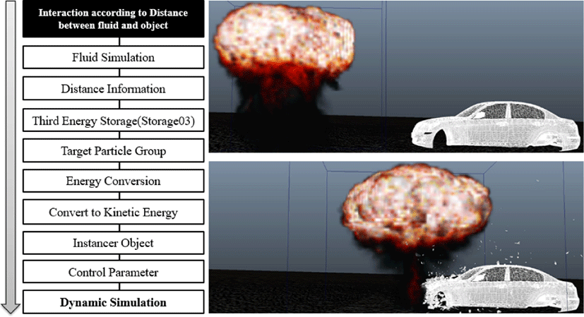
First, the distance between each particle of the target particle group and the fluid was measured. The fluid was visualized in the 3D container through a high number of voxels, so calculating the distance between each of the particles of each target particle group would result in excessive computation cost. Thus, only the distances between the closest particles of the target particle group (closest particle group) and objects were calculated. The distance between each of the particles in the closest particle group and each of the particles in the target particle group was calculated for each frame. Each particle was given a third energy storage property (henceforth referred to as Storage03) that contained two parameters. The first parameter controlled the point of interlink according to distance limitations while the second applied the critical point to object motion. Distance values were only calculated for fluid and object particles whose distance was below a certain threshold to optimize the process.
After the explosion occurred, the fluid approached the object. In the experiment, the destruction effect occurred only for objects whose distance from the fluid was below a certain threshold. The results of Experiment 1 and 2 were referenced to determine this threshold, which was set so that motion occurred only after a certain amount of time passed after the fluid came into contact with the object. The experiment was also designed so that no destruction effect occurred when the distance between the fluid and the object was above the threshold. The results of Experiment 3 showed that interlinking the explosion and destruction effects by the distance between fluid and objects resolved the issues observed in Experiments 1 and 2.
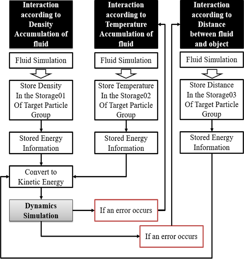
Based on the results of the mentioned experimental study, an experiment with naturally interlinking explosion and destructive effects was conducted. Fluids were generated by container (Size: 30, 30, 30/Resolution: 60, 60). The basic density of the fluid was set to 20 Density/Voxel/Sec, the temperature was set to 12 Heat//Voxel/Sec, and the fuel was set to 7 Fuel//Voxel/Sec, and external factors were given a value of 9.8, turbulence 2, and noise 0.2 to form a blast effect. The body used in the experiment was pre-split through the Voronoi diagram and converted to an instancer. Through the explosion simulation, the particles of each instancer objects accumulate density and normalized temperature values from the fluid and store the distance from it. Parameters were set to specify the critical point at which the destruction effect occurred in density, temperature, and distance, and objects that reached the set value started destructive motion under the influence of Radial Field (Magnitude: 5, Attention: 1), an external force applied to the body. Groups that failed to perform movements due to a rapid disappearance of density were designated to fulfill movements by temperature accumulation. Groups with errors in which density and temperature did not maintain proper values at certain points due to the influence of turbulence were designated to perform destructive movements when the distance between the fluid and the particles approach a certain level or more. The manufacturing process was experimented so that the destruction effect due to the explosion effect could occur in a chain connection more efficiently and accurately by minimizing errors according to the pipeline design above, and conducting a comprehensive verification based on density first, temperature second, and distance last.
Three experiments were conducted to test methods of interlinking explosion and destruction effects by energy accumulation and conversion. The first tested the effect of interlinking the effects by fluid density, the second by temperature, and the third by the distance between the fluid and relevant objects. In Experiment 1 using fluid density, some objects did not move because the fluid dissipated, so Experiment 2 was conducted using temperature. In Experiment 2, voxels had incomplete information because turbulence caused the fluid to have irregular motion, so Experiment 3 was conducted using the distance between the fluid and relevant objects. In conclusion, three experiments were conducted to determine the effectiveness of different methods of interlinking explosion and destruction effects. The overall experimental process is shown in Fig. 12.
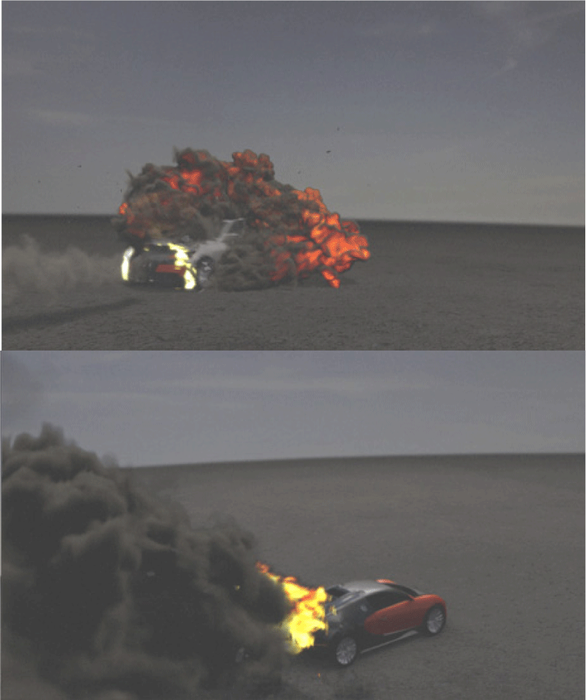
The distance method used in Experiment 3 produced more accurate results than the density and temperature methods used in Experiments 1 and 2, respectively. However, the distance method requires more data processing than the other two, making it less efficient. Thus, the most effective and efficient method for interlinking the two effects is to use fluid density and temperature for all of the particles and only apply the distance method to particles that do not behave properly. The final result of the experimental process (with lighting and rendering) is shown in Fig. 13.
III. CONCLUSION
Producing complex explosion and destruction effects requires a high level of training and time because it requires separately simulating and then integrating them. Thus, in the present study, experiments were conducted to test methods of producing both effects simultaneously by combining explosion effects made through fluid simulations and destruction effects made through dynamics simulations. The experiments tested interlinking the explosion and destruction effects according to fluid density, fluid temperature, and the distance between the fluid and relevant objects. The results of the experiments showed that each of these methods can interlink the effects. In the present study, experiments were conducted to test methods for efficiently creating explosion and object destruction effects by interlinking them in fluid simulations. However, this study did not conduct experiments related to related effects, such as dust and the fluid’s collision with the ground. As such, further research should be conducted to identify methods for interlinking these effects as well in order to develop an integrated visual effect production method.