I. INTRODUCTION
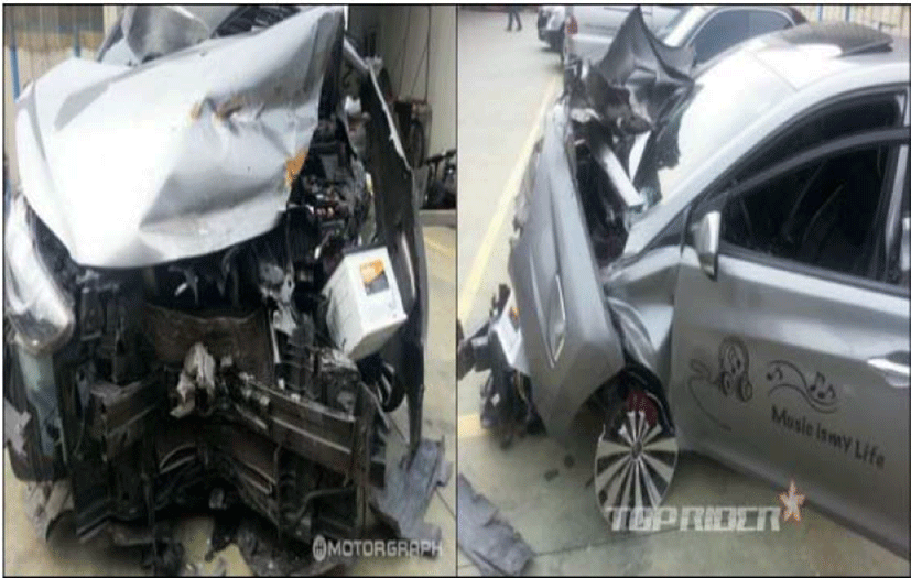
Many cases of inoperative airbags have been reported globally over the last few decades and it was a pity to see the cynical articles on all sorts of internet communities in the Republic of Korea saying that the airbags installed in the Korea H Company’s T cars are useless. One of the A Korean newspaper says: “Last 14th of July 2015, a driver who was driving H Company’s T cars died from the car crash. Although it was presumed that the driver was dozing off while driving, the actual cause is still unknown. None of the six airbags were activated. If they had, the driver would still be alive. H Company’s explains that the speed of the victim’s car was under 30km/h for both primary and secondary collisions so the speed did not meet airbag activation requirements.” Figure 1 shows an example of defective airbag from the crash.
The aim of this paper is to aid the drivers in easily checking and recognizing the possibility of airbag actuation for existing cars. Now that a smart car has become one of the major social issues around the world, developing the application that detects faulty or worn out airbags installed in the decrepit cars is the first attempt. The application focused on old-model cars. Among these cars, the airbags of the container vehicles had serious problems. Also, there have been many cases of accidents caused by the defective airbags regardless of car models. Skipping regular maintenance was one of the causes.
In this study, the related researches are introduced in Chapter 2 and the descriptions of the proposed application/system in Chapter 3, followed by conclusion and future work in Chapter 4.
II. RELATED RESEARCH
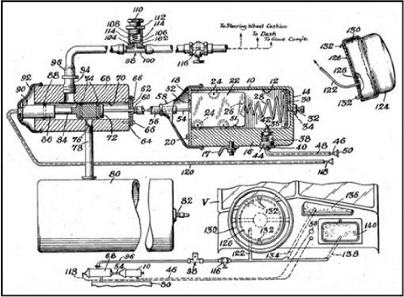
Even though the role similar of an airbag appears to that of seat belts, they are different. Seat belts prevent the passenger’s body from springing out but airbags usually protects upper the body, especially the head. If a driver neglects to fasten his/her own seatbelt while driving, it is most likely that the body will be dragged down under the dashboard in an accident [1-6]. Moreover, he/she could suffer more damages by hitting an expanding airbag. Therefore, one must wear a seatbelt at all times while on the road. In some cases, seatbelts might wrap around the neck during side impacts but still, it is safer to wear them. Actually, airbags can be considered as the supportive restraint devices for seatbelts. To examine the parts and components of an airbag system briefly, it is largely divided into three parts: sensor(s), processing unit and the body main body. Figure 2 shows Early Airbag Model.
Basically, an airbag system is composed of a sensing system and an airbag module. The former is comprised of sensor(s), battery and diagnostic unit and the latter, with airbag body and operating gas expansion device.
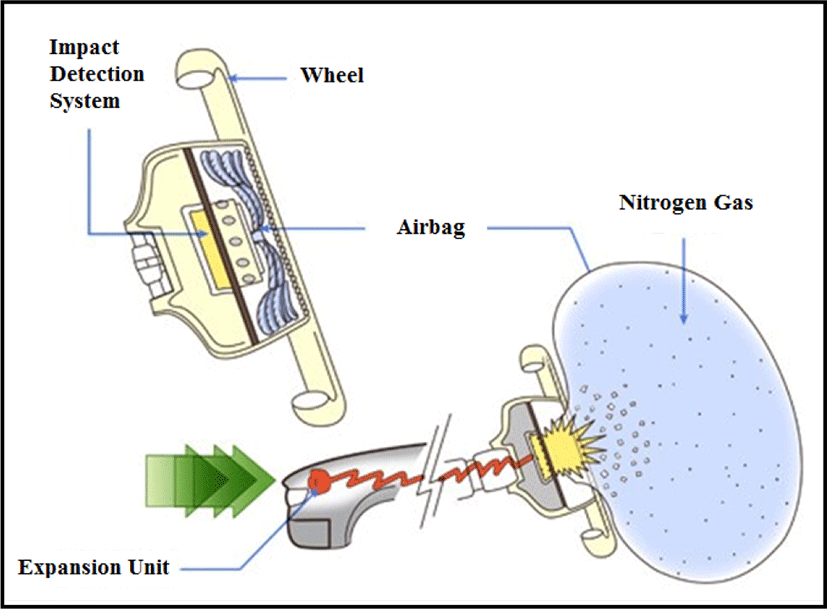
The high-pressure gases which are usually generated from rapid combustion of a certain solid matter or a gas stored in a high-pressure container is used for the airbags. Figure 3 shows airbag module.
There are slight differences in the operating conditions of airbags depending on the types of cars and airbags but they deploy when the effective impact speed exceeds 20-30km/h and the collision angle is within 30 degrees from left or right front of the car. Then, how do they unfold? Airbags are comprised of a gas expansion device that inflates the airbag, an impact detection system and airbag module including airbag body.
The impact detection system consists of impact electronic sensors such that the roller of the impact sensor will slide forward and push the activation switch in a split second of collision exceeding a certain speed, following the law of inertia. Electricity will flow through the circuit leading to an explosion at the gas generation unit and the time for such process is about 0.01sec. Once ignited, nitrogen gas will be generated and it enters into the attached airbag in an instant. This process, takes about 0.05sec for the folded airbag to fully unfold. The volume of contained nitrogen gas is approximately 60L and such a large quanhty of gas inside the airbag cushions the impact and makes it possible to avoid a mortal injury resulting from the primary collision. As for the impact sensors, there are Electronic Front Sensing (EFS) sensor and Side Impact Sensor (SIS). Additionally, the seat-position sensing sensors, passenger classification sensors and other sensors like ones that check the safety belt wearing statuses of passengers can be included depending on each car type. A calculation was made for the following airbag system on a condition of an effective impact speed of about 20-30km/h and considering that, only the one-dimensional head-on collision incident has been chosen.
CAE refers to the process of analysis and interpretation using computers and generally defined as the Engineering Simulation. Based on the product’s 3-dimensional model created on a computer, an optimal design will be determined and drawn up by evaluating model’s functions and performance level. That is, CAE is a new technology that applies computers for product design or development; can significantly reduce the test time and cost through computer-aided simulations; and has a concept of integrating whole process of engineering analysis and interpretation, cost analysis, product planning and process control. Behind the widespread use of CAE application is to achieve an engineering environment where the problems following the shortage of skilled engineers due to diversification and sophistication of development items, frequency of redundancy, and frequent design changes can be minimized.
The aim of this task is to develop an application that can check the operability of airbags focusing on the mechanical calculations in respect that most of airbags are deployed at the speed around 20-30km/h.
There were many mechanical elements in the conventional sensors installed in the existing vehicles but as the requirements in the vehicle system increased, many types of sensors that use the Micro Electro Mechanical System (MEMS) technology have emerged recently to deal with them. Currently, small-sized and low-priced but highly efficient sensors integrated with highly advanced semiconductor technologies are being mass-produced [7-9]. The vehicle sensors these days play a key functional role in determining the current state of the vehicle and detecting the problems on a real-time basis, being distributed in every corner of the vehicle as a neural network. Additionally, as they are linked with an intelligent control system in a network, the electronic control system becomes more sophisticated. It is expected these types of vehicle sensors will occupy a big part in the electronic components industry.
The technical development trend of the vehicle control system has shifted from mechanical to electronic control over the past few decades, during which the systemization between electric/electronic parts, modularization of parts, and integration of electronic parts accelerated [7-9]. The role of sensors that deliver reliable information about real-time vehicle operational state and all sorts of physical quantities accurately and in detail to the electronic control unit (ECU) is becoming more important.
Since vehicle sensors are demanded to operate in harsh conditions, they need to have high reliability and satisfy the requirements of being multi-functional, high performance, and less costly. The vehicle sensors normally operate in the temperature range between -40 to 125°C but the engine oil pressure sensors are used in the temperatures between 120 to 130°C while the exhaust sensors must withstand up to 800°C [7-9].
The development in semiconductor technology can contribute in providing the solutions that satisfy such various requirements and many high-quality vehicle sensors are being continuously manufactured as the MEMS technology-based semiconductors developed.
Recently, the sensing devices are becoming smaller and denser as the use of semiconductor devices have increased due to the development of microfabrication and IC fabrication technologies based on the cutting-edge technologies such as MEMS and NANO technologies. For instance, in some of the detection sensors, signal processing and network micro control units (MCU) are integrated with the detection unit [7-9].
As for the vital characteristics of vehicle sensors, they need to satisfy the high-standard requirements such as sensitivity, linearity, stability, and reliability. As far as reliability is concerned, the sensors are required to have not only the mechanical reliability against temperatures or vibrations but also the electromagnetic reliability such as electromagnetic immunity and antistatic capability, following the ever-progressing “vetronics”.
It is currently expected that an innovative technological development will continuously progress as sensor technology is integrating with rapidly developing MEMS and NEMS (Nano Electro Mechanical System) technologies [7-9].
Sensors are becoming smaller and cheaper due to the adoption of semiconductor technology and increased production rate. The development in integration technology has led to the emergence of multi-functional components which provide a variety of functions in a single device. The multi-functional and intelligent ‘smart sensors’ were developed following the birth of a semiconductor system chip with the integrated sensor system where various types of sensor devices, circuits, communication devices, and microprocessors are linked and interacting. These sensors can be installed in any locations in a vehicle depending on their uses [7-9].
The electric/electronic systems for the vetronics require faster sensor processing time and more efficient memories. These requirements led to development of the smart (intelligent) microprocessors. The integrated vetronics system is comprised of sensors, MCU, and power chips (semiconductors), interacting with each other to detect the external/internal vehicle information, process signals with MCU and deliver them to the ECU through their network to be analyzed. The ECU will then control the vehicle’s actuator based on the analysis results. Following the improvement in the degree of integration using nano-technology, it became possible to realize the technologies once believed impossible. For example, the existing gas sensors’ detection limit was a few tens of ppm but after the introduction of the carbon nanotubes, it became possible to make measurements up to several ppb [5-10].
The commercialization of semiconductor-type vehicle sensors started from the Manifold Absolute Pressure (MAP) sensors for the engine control purpose, but they are currently being used mainly for the safety/comfort systems including airbag and navigation, systems, ABS, and Electronic Stability Program (ESP). Especially, the mandatory installation of airbags and the Tire Pressure Monitoring System (TPMS) along with the standardized use of ESP have led to increased demand for the semiconductor sensors [7-9].
III. A DESIGN OF BASE TECHNOLOGY FOR AIRBAG ACTUATION CHECKING APPLICATION BASED ON MECHANICAL CALCULATIONS
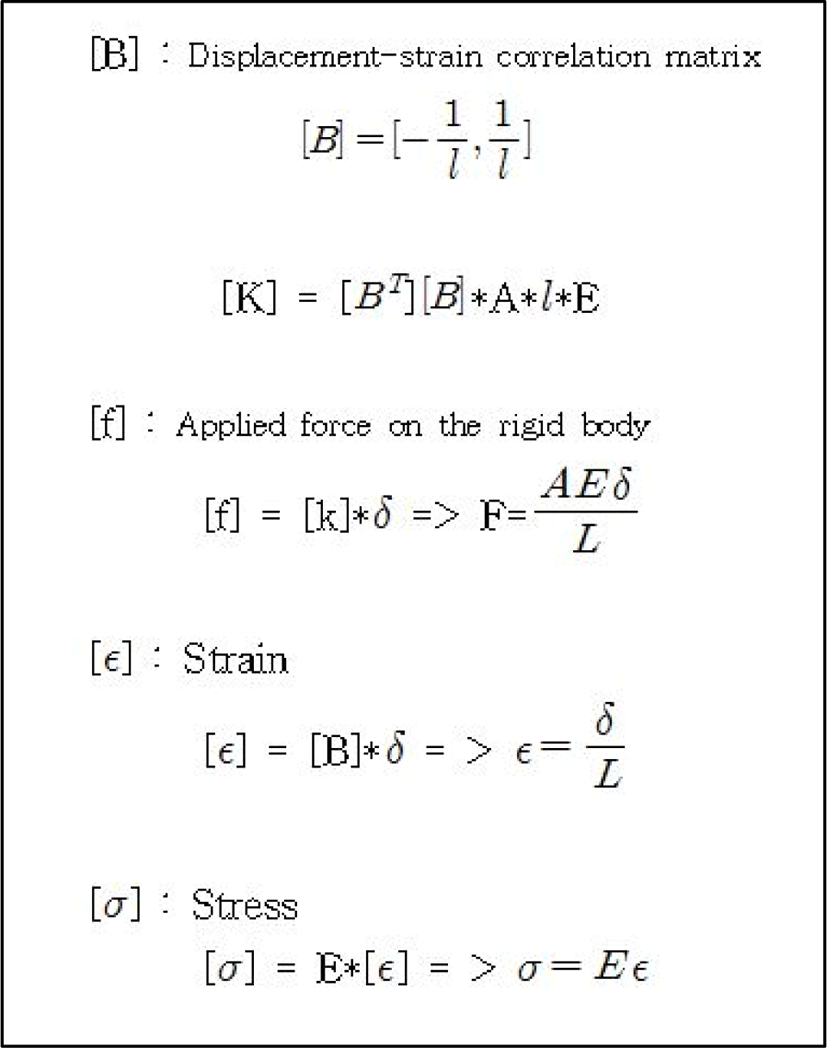
In CAE, the local coordinate system that sets the parallel line(s) equivalent to the product as its standard is used. The rigidity changes in accordance with the angle of applied force. Even though there are various forms of mechanical structures, only the interpretation of tension and compression will be used in the application.
Used elements are: Input value: A (area: cm2), (length of rigid body: cm) E (modulus of elasticity: kg/cm2. Derivation process is as following. Figure 4 shows elements. And the example of modulus of elasticity is shown in Table.1
| Metal | Modulus of elasticity (E) |
|---|---|
| Copper | 1.25 |
| Aluminum | 0.72 |
| Iron | 2.15 |
| Gold / Silver | 0.81 |
Area, length of rigid body and modulus of elasticity have been set as the basic property values for the calculation by the application [6-8] and as shown in Fig. 5, the buttons No.1 to No. 3 are to be used to check each phase. For this process, Java Android was used for the design and its implementation. Respective property values can be entered whenever necessary. The possibility of airbag troubles can be detected by calculating the parameters.
The possibility of airbag trouble will be determined after receiving an input value from the user, as Fig. 5 & Fig. 6. Currently, we are developing a function that refers the users to nearby repair shops when the airbag is faulty or has a possible malfunction, along with a technology in which the sensor transmits the value when it is installed in the main body of a vehicle. These will be discussed in ‘future work’. In addition, the standards for value calculation and threshold setting will be disclosed in a future study after patent registration.
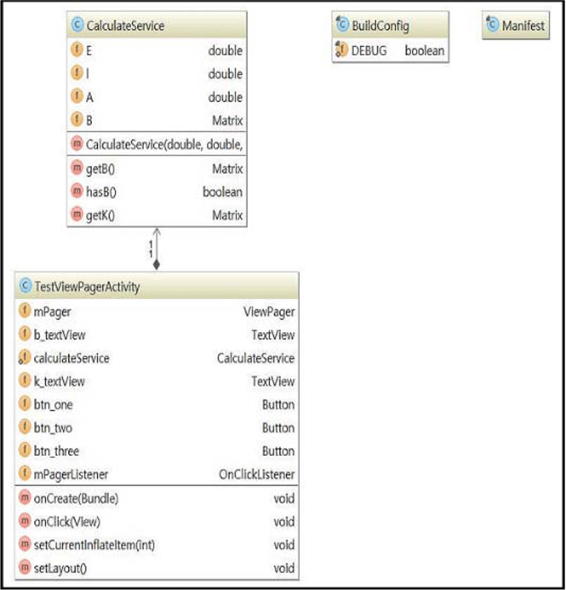
The design and implemented UML (Unified Modeling Language) are described in Figure 7, where the calculation elements can be found. After calculating the result value of the force, it calculates impulse with this value. Then it will be possible to apply impulse as an airbag activation requirement.
IV. CONCLUSION AND FUTURE WORK
There were some major reasons for the inoperative airbags. First, in case of real collisions, human bodies move backward due to impact reaction so that the sensor will not make detection appropriately, even in a serious crash. Second, the cases involving mis-calculation of impulse by the sensor(s). Most of the time, even the experts conclude that the cause is unknown or the problem does not lie on the sensor(s). Many other recognizable or unknown reasons also exist, but not being able to receive protection by the installed airbags from such reasons could lead to a fatal death instead of some minor injuries or disabilities. An exact impulse calculation condition is required to solve this situation and the proposed application can be the first step in providing the solutions.
The application proposed in this paper is one that can be applied to head-on collisions but it can also be used for the rear-end collisions just by reversing the system operation direction, solving the problem resulting from the first cause. The impact force can be estimated by evaluating the degree of damage of the car installed with relevant airbags and the impulse will be determined for airbag deployment. In this way, once a directional element is added, application’s precise calculation will be able to protect users (drivers) with their airbags even if a collision occurs from unexpected directions. Moreover, since this application also has a function of estimating the impact force through evaluation of deformation of car body instead of the major function of common airbag sensors usually activated by the impulse transmission or by inertia, a better protection can be expected. We also expect that our system will aid in designing safer cars by examining vehicle safety through the safety tests based on the stress analysis. Our future work involves test bed experiments for an actual car. If airbag detection for the decrepit vehicles can be carried out perfectly, the accidents will be prevented and it will also be possible to apply the technology to ships and aircrafts as they might be still operational in coming decades. Using the technology for the reefer containers could be another option.
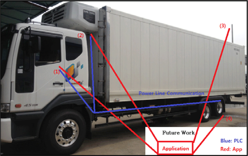
For the future work, and in the short run, the author will attempt to identify the problems by establishing communications lines in a decrepit reefer container vehicle using the Power Line Communication (PLC) technology as described in the preceding studies [10-11].
Figure 8 shows the concept. It is regrettable that only the part (1) has been completed but in the long run, the future work will be continued for the aircraft application, after designing the system for the use in the ships in the preceding study [12-13].
