I. INTRODUCTION
Recently, it has begun to take the spotlight of smart traffic, and as it has been a long time, there is a foothold for building smart cities such as autonomous vehicles and smart signals. Because of this, there is automation technology, and it is necessary to work to miniaturize the technology so that it can be applied more and more in real life. Intelligent transportation systems are continuously being introduced and use of existing CCTVs or black box systems to recognize the number of vehicles is also increasing. Research is accomplished on how to quickly detect license plates, and the results of these studies are being applied to actual products. Smart vehicle plate detection is an essential technology to find out the information of vehicles in operation. By detecting the vehicle plate area, it is possible to recognize the vehicle number in the vehicle plate area, thereby acquiring and utilizing the information of the vehicle and the driving information.
Methods of detecting the features of the outside of the license plate in the color image were mainly used for recognizing a vehicle plate. R. Zunino [1] proposed a method of detecting a vehicle plate region using window segmentation and vector quantization. This method detects an area with a large change in brightness and divides the license plate area into blobs. The method has a disadvantage in that it is difficult to construct a blob when the plate is long distance. A method of generating the respective fuzzy maps for the edge and color components of the license plate area and detecting the license plate area through fuzzy inference was also studied [2]. A method of vehicle license plate detection using a Haar-like feature [3] constructed a chain weak classifier to learn the morphological arrangement of characters in the license plate. A method of detecting license plate areas by learning local binary patterns of license plates[4] was proposed. However, these methods using color videos had the disadvantage that it was difficult to apply these to real life due to phenomena such as rotation and perspective projection distortion accompanying a change in screen attitude. There were also computer performance issues, so the methods were hard to apply to real situation.
In this paper, we provide a method of detecting a plate with a depth image in order to overcome the weaknesses of illumination change and camera attitude change in plate detection using color images. When a depth camera is used to recognize an object, an infrared sensor of the depth camera determines a value obtained by measuring the distance between the object and the depth camera as information. Recently, methods of object recognition through depth videos [5-7] have been studied.
Due to the structural characteristics in which the plate is planarized, it is possible to regard an area composed of similar planes as a license plate candidate area of a vehicle. After dividing the image into square shaped blocks for detection of planar areas, the depth information in each block can be used to obtain information of its surface and the first near plane. If the in-block plane error is less than a certain value, the block is considered to be planar. Thereafter, the normal vectors of the planes between adjacent blocks are compared to measure the degree of similarity. If the degree of similarity between the two blocks is high enough, it can be considered that the two blocks were performed in the same plane. Therefore, the plane area in the image can be obtained. The actual size of the area is then measured using depth information and if the actual height and width of the measured area is similar to the size of the actual plate, the area is considered as a plate area. For each labeled plane area, the actual size of the plane can be measured through a depth image. The width of the plane can be obtained by converting the distance into camera coordinate distances for each pixel at the left end and each pixel at the right end of each labeled area. For each pixel at the top end of the area and at the bottom end, the height of the corresponding plane can be obtained in the same way. If the width and height of this measured plane area match the width and height of the actual plane, the area is detected by the number plate. The method proposed in this paper can be used to perform vehicle plate detection independent of the lighting environment.
II. Vehicle Plate Recognition Using Depth Camera
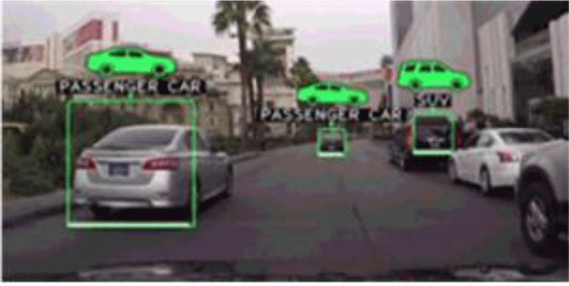
In the case of vehicle plate detection using RGB images, the contrast of the vehicle plate, the color difference information and the morphological information of the edge are used with the actual information of the surface of the vehicle plate and the actual length of the vehicle plate as shown in Fig. 1. It is possible to easily obtain information on the surface and the actual length between two points by using the depth information that indicates the distance to the camera.
A relationship between a pixel p≡(x, y) in the 2D image coordinate system and a point pc≡(xc, yc, zc) in the 3D camera coordinate system is represent as Eq. (1) [1].
where f means a focal length that is such of the camera parameter and d means a depth pixel value of p.
In order to detect a plane area using depth information, 2D image coordinates of depth pixel should transform to 3D camera coordinate system.
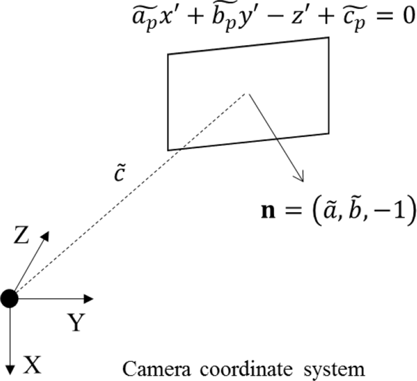
A plane containing a point (xc, yc, zc) on a 3D camera coordinate system is represented as follows:
where ap, bp, cp are plane coefficients that determine the plane.
The following matrices are obtained by substituting points in an N×N block into Equation (2):
where (xci,yci,zci) mean coordinates of it point in the block and n means the number of point in the block. If n is more than 3, a plane that has the smallest distance from the given point can be obtained by finding plane coefficients through following equation:
where A+ means a pseudo-inverse matrix of A that is calculated by following equation:
In Equation (2), a normal vector is (ap,bp,−1), and a distance between an origin of the camera coordinate system and the plane is cp as shown in Fig. 2.
If both planes are similar, normal vectors and distances of the planes should be similar. Therefore, the plane similarity between the adjacent blocks can be measured by comparing coefficients of the modeled planes of the blocks.
In order to measuring the plane similarity, the angle between normal vectors and a distances difference between the planes are calculated by following equations:
If δ12 and ε12 satisfy Equation (7), the planes can be considered to be similar planes.
where U and D mean thresholds of the angle between normal vectors and the distance difference. If a pair of modeled planes for two adjacent blocks satisfies equation (8), the blocks are grouped into a same plane.
The outlines shape of each grouped plane area is extracted in order to find rectangle object. If the shape of the outline is similar to the shape of a polygon with four corners, the area becomes a vehicle plate candidate as shown in Fig. 3.
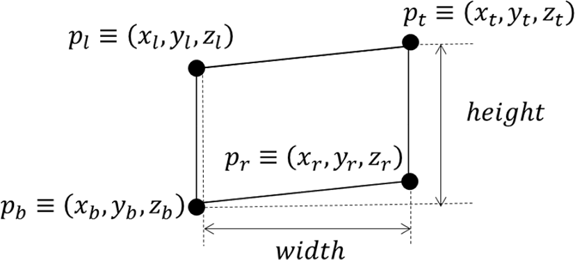
Actual width and height of each vehicle plate candidate are measured through the depth information. Image coordinates of 4 pixels at the top-most, bottom-most, left-most, and right-most of the candidate area are transformed to 3D camera coordinate through Equation (1). The width and height are measured through following equation:
where (xt,yt,zt) mean the 3D coordinates of pixels at the top-most as shown in Fig. 4. If the width and height is matched to the vehicle plate, the area is detected as the vehicle plate area.
III. Simulation Result
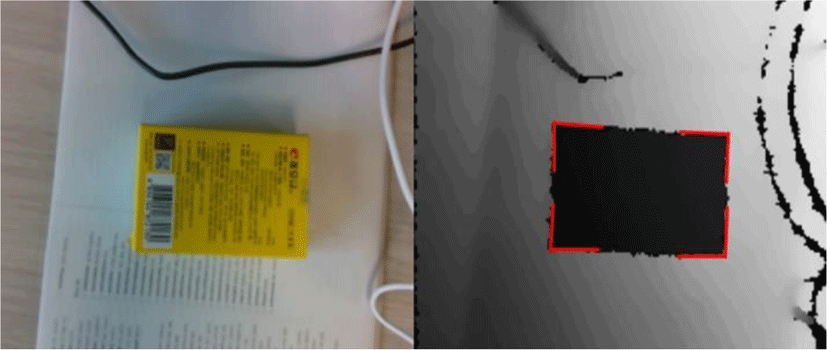
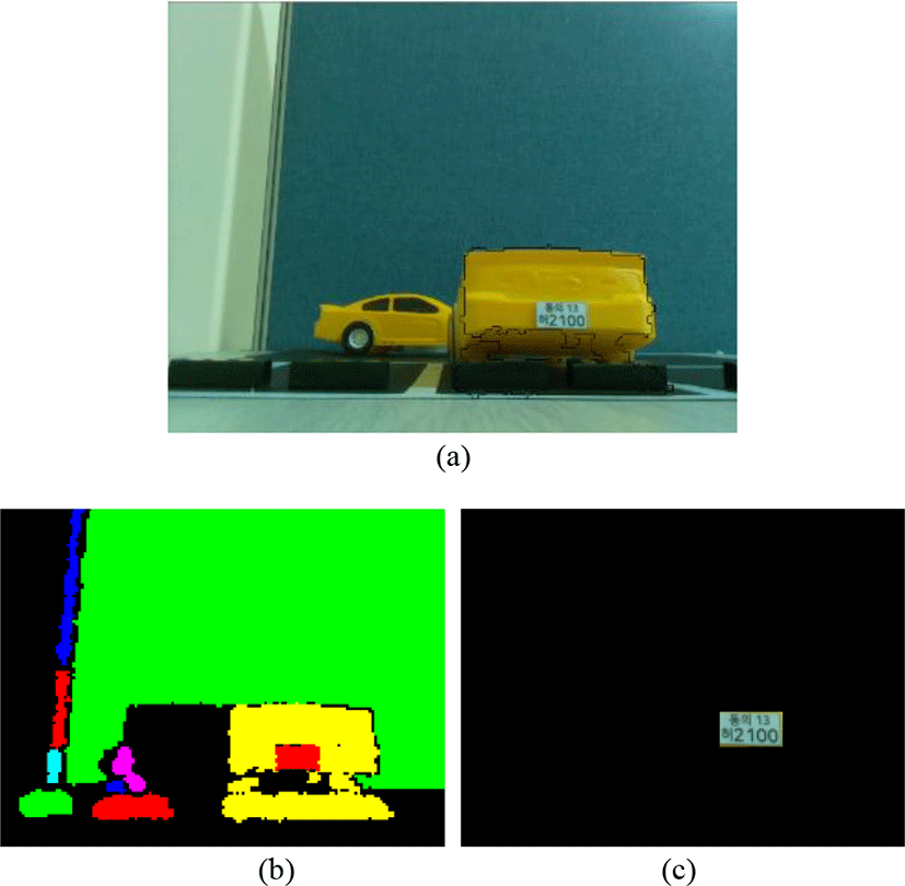
In order to measure a performance of vehicle plate recognition through the proposed method, we use a manufactured car model with a vehicle plate. Results of the vehicle plate recognize through the manufacture car is shown in Fig. 5.
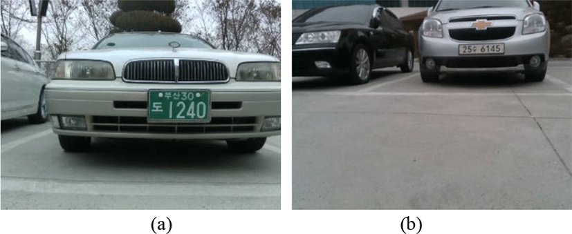
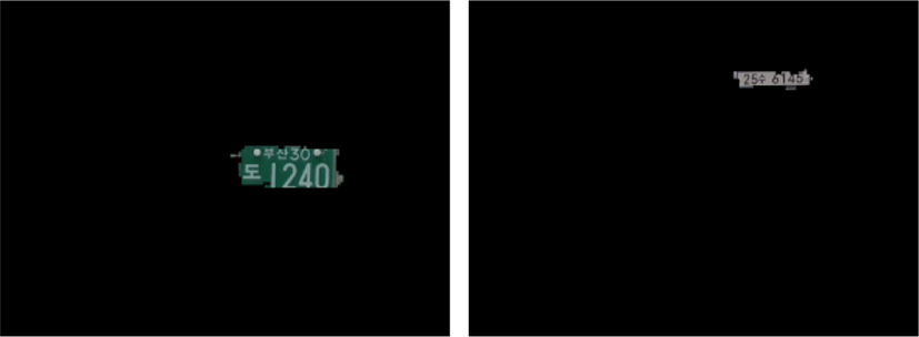
In order to measure the performance of the proposed method, we use 20 depth pictures including vehicles with a Korean vehicle plates are captured such as Fig. 6 for simulation. The depth pictures are captured by Intel Realsense D435 whose resolution is 320x240 and focal distance f used in Equation (1) is 423.5. The width and height specifications of Korean vehicle plates are shown in Table 1.
| Vehicle plate type | Width | Height |
|---|---|---|
| General vehicles produced before 2006 | 335mm | 155mm |
| General vehicles produced after 2006 | 520mm | 110mm |
Table 2 shows successful recognition rates of vehicle plate recognition according to D and U as shown in Fig. 7. When D and U are 50 and 0.95, respectively, the recognition rates are best. The recognition rate is more accuracy for the vehicle plates that are produced after 2006.
| Plate type | D | U | Detection accuracy(%) |
|---|---|---|---|
| Before 2006 | 30 | 0.95 | 85 |
| 30 | 0.98 | 92.5 | |
| 50 | 0.95 | 87.5 | |
| 50 | 0.98 | 95 | |
| After 2006 | 30 | 0.95 | 75 |
| 30 | 0.98 | 92.5 | |
| 50 | 0.95 | 77.5 | |
| 50 | 0.98 | 97.5 |
IV. Conclusion
In this paper, we proposed a method of recognizing vehicle plates through capturing depth pictures. The existed methods of recognizing the plates through a color picture had a problem that it were affected by lighting environment, but the proposed method can recognize the vehicle plates more accurately. We expect that the proposed method will be possible to improve the intelligent traffic system by recognizing the vehicles and license plates more quickly and accurately.