I. INTRODUCTION
In recent years, researches on the mobile ad hoc network (MANET) have been actively conducted. MANET does not use any infrastructure, and it is a network formed by a wireless node that uses multi-hop communication technique. Multi-hop communication is a technique that a node communicates with another node that is out of direct communication range by transferring the packets through relay by the other nodes. Taking advantage of these features, driver assistance, disaster prevention, crime prevention, disaster measures, the environment and energy measures, application in the field of elderly care and medical care are expected.
MANET has several specific issues. Because it is composed of wireless nodes, the lifetime of the network largely depends on battery life of the nodes. Though various routing protocols are considered, the improvement on these protocols is still needed for practical use of them.
As one of these routings, there is the one using the location information. This routing protocol has advantages that network load due to control messages for route construction is small and route determination process is simple. Each node can reduce the amount of control packet at the time of route construction request by determining the relaying node based on the position information of the destination included in the packet. However, decreasing load for managing position information has become challenging issue. Therefore, a central management method of location information using the mobile agent has been proposed [1] [2].
In these methods, the nodes in the network transmit the location information to mobile agents that are set in a specific area in the network. Since mobile agents have the position information on all the nodes in the network, it is possible to build a suitable route for packet transmission. Further, it is possible to adapt this method to the expansion of network size by using multiple mobile agents [3]. This method dynamically changes the number of mobile agent depending on the network situation and can improve the network performance [4]. However, because the area where each MA manages is not always appropriate, the number of nodes that the MA manages is not uniform. This would increase the network load due to unnecessary division and integration of MAs.
To solve this problem, in this paper, we propose an enhanced method. In the proposed method, the MA management area is properly determined using the position of all the nodes. To show the effectiveness of the proposed method, we evaluate the performance by comparison of the conventional method with the proposed one by computer simulation.
II. RELATED WORKS
A mobile agent (referred as MA) is defined as the agent that consists of computer program and data and can migrate from one node to another node autonomously. MA was originally developed as a distributed system of a wired network [5] [6]. However, in recent years, methods for using MA efficiently in wireless multi-hop network have been proposed [7] - [10]. An MA migrates among nodes within a circular area known in advance by every node. In this method, the network area is divided into plural sub areas with one MA in each. The MAs receive and update location information from nodes existing in their sub area. In addition, the MAs receive route requests from nodes and calculate a suitable route that will be sent back to requesting node.
A node sends a location update packet to the MA when it moves a distance exceeding a threshold. The packet containing the location information update is only sent to the MA, thus the amount of update packets can be reduced. Update packets are sent using the forwarding by GEDIR [11]. In this forwarding algorithm, a packet is transmitted by selecting the closest node to the destination as the next hop node.
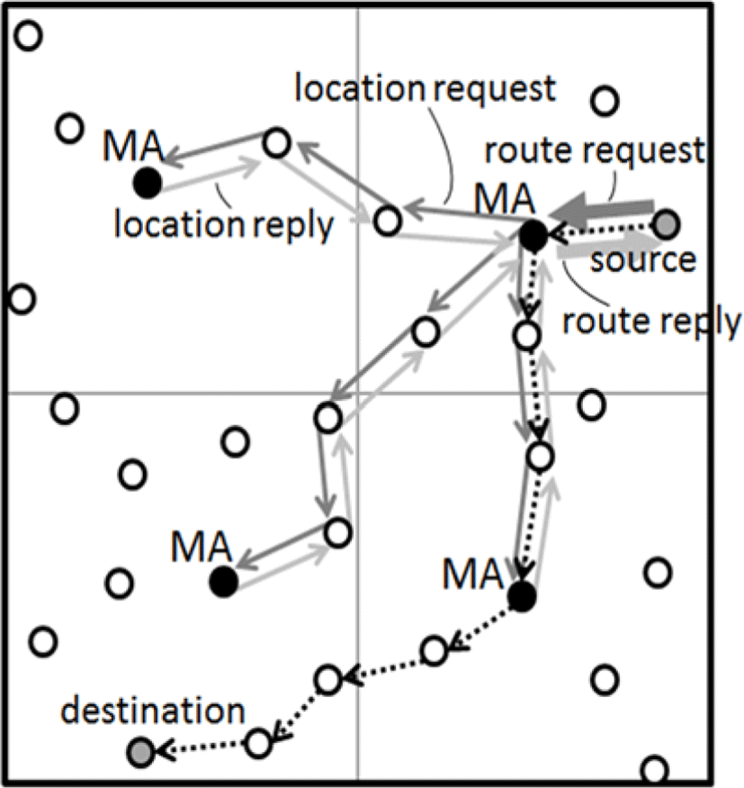
As shown in Figure 1, a source node first sends a route request packet to the MA managing its sub-area. In the case where the destination and source nodes are in the same sub-area, this MA then calculates the suitable route according to the process described in the following subsection 2.1.4 and sends back the route reply packet to the source node. In the case where the source and destination nodes are in different sub-areas, the MA sends a request packet for the destination node to the MAs of others sub-areas. Then, it sets a timeout and waits for all the other MAs to send a reply packet containing nodes’ location information in their area. When all MAs send back the reply packet or the timeout expires, the MA in the source node’s area calculates the route. If it could obtain a route, it sends back a route reply packet including the information to the source node. Considering loss or delay of location information updates, the MA waits three times of timeout for receiving reply packets from all others MAs. If the third timeout expires and the MA cannot still calculate any route, it sends only the location information of the destination node to the source node.
The MA uses the Dijkstra’s algorithm for the route calculation. The Dijkstra’s algorithm is an algorithm for finding the minimum cost path between two points efficiently. First, by using position information of the node the MA has, it calculates whether communication link between two nodes is present or not. By calculating for all combination of any two nodes, it can obtain the network topology. Setting cost of all links to be 1 and applying the Dijkstra’s algorithm, it can obtain the shortest path from source to destination.
In most of routing protocols using position information, a node sends a packet by forwarding algorithm using position information of the destination node. On the other hand, in this method, the source node can obtain from the MA not only the position of destination but also the shortest path. Therefore, each node uses the path prior to the position of the destination.
The number of MAs dynamically changes depending on the number of location update messages in this method. This number is relative to the number of nodes in the network and their speed. When the number of location update messages in an MA increases and reaches a threshold, it starts process of splitting. First, two copies of the MA are created and sent to their new locations and it sets a timeout. When the timeout expires, the MA sends a flooding packet to inform all the nodes in the network of these two MAs’ positions. Then it is deleted, and the newly created MAs begin the location management and the route construction. Each node in the network sends location update packets to the nearest MA.
Contrary to the splitting of MA, when the number of location update messages decreases to a threshold it starts merging process.
First, one MA (MA1) sends a merge request packet to the adjacent MA (MA2). When MA2 received the packet, it checks if its number of location update packets is also less than the threshold. If so, it sends a reply packet to MA1 and sends a copy of itself to the merging point. When MA1 received the reply, it sends a copy of itself to the same merging point. After merging of these two MAs at the merging point, this MA sends a flooding packet to all the nodes in the network. When MA1/MA2 received the packet, it is deleted and the new MA manages the network. The way of route construction is the same as that in the conventional method. With dynamical changing of the number of MAs, a node may have trouble for finding the MA to which it sends packets. Therefore, if a packet from a node cannot arrive at any MA, an error packet is returned to the node. In this case, it sends a one hop broadcast packet to gather updated information location about all the MAs.
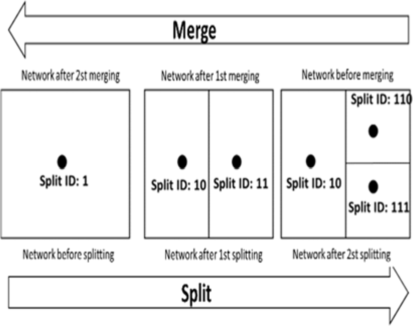
This method defines the binary split ID to distinguish the level of split and merge of MAs. The initial value is 1. When the splitting occurs, single digit is added to the end of the ID, and the lowest digit is deleted when the merging occurs. Thus split ID is uniquely determined and it is guaranteed that the ID of any MA never overlaps with that of any other MA. The split direction is decided according to the number of digits of the split ID. If the number of digits is odd the area is split horizontally, otherwise the area is split vertically. The positions of created two MAs, MA1 and MA2 are calculated as follows:
Horizontal split:
Vertical split:
Here, “a” is the length of the long side of the sub-areas before the division. (x, y) is the position of the original MA. Examples of this method are shown in Figure 2.
III. PROPOSED METHOD
In the conventional method, the area where an MA manages is not always appropriate. This would increase the network load due to unnecessary split and mergence of MAs. To solve this problem, we propose an enhanced method, in which the MA management area is properly determined using the position of all the nodes.
In the proposed method, the boundary of the sub areas is determined dynamically at the time of the splitting process using the position of all the nodes. When the splitting is horizontal one, the boundary is expressed as the horizontal straight line with the average y value of position coordinates of all the nodes in the sub-area. In the case of vertical splitting, the boundary is expressed as the vertical straight line with the average x value of all the nodes in the sub-area.
The positions of created MA1 and MA2 are calculated as following equations.
Horizontal split:
Vertical split:
Here, x1, x3 and y1, y3 is the coordinates of the opposite ends of the area. Further, x2 is the average value of x values of the position coordinates of all the nodes and y2 is the average value of y values of the position coordinates of all the nodes.
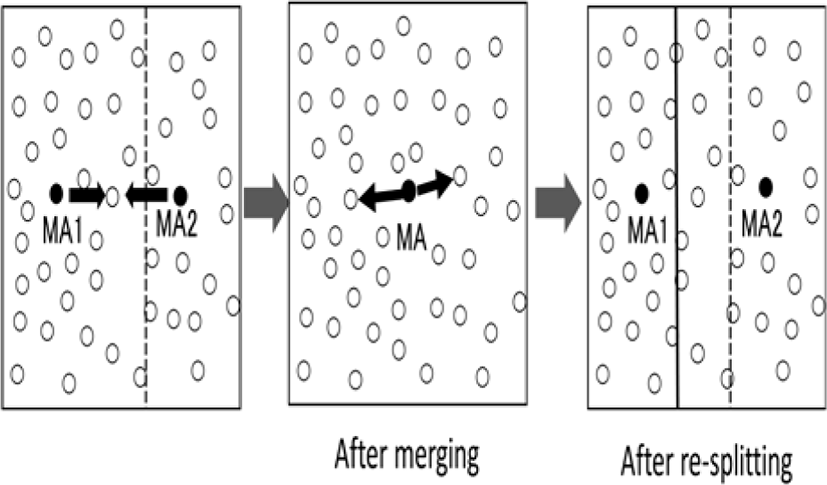
In the conventional method, merging of two MAs begins only when both of them satisfy the condition to merge. On the other hand, the proposed method begins the merging process if at least one MA satisfies the condition to merge. Then, after the mergence, the MA immediately determines whether it should split again or not based on the sum of the received position update packets of the two MAs before the merging process begins. The image of the merging and the re-splitting is shown in Figure 3. Here, the dotted line is an example of boundary before merging and the solid one shows the one after re-splitting.
IV. SIMULATION MODEL
In the simulation, nodes are deployed at random with a density of 500 nodes/km2 within a square area of one side 2000 m. All the nodes move toward the unevenly selected destination. Also, a randomly selected node sends a 500 Kbytes UDP flow to another node at a frequency from 0.2 to 0.8 flows/s. In Table 1, we show the other simulation parameters. In each simulation, we evaluate the arrival rate of UDP packets and the average transmission delay.
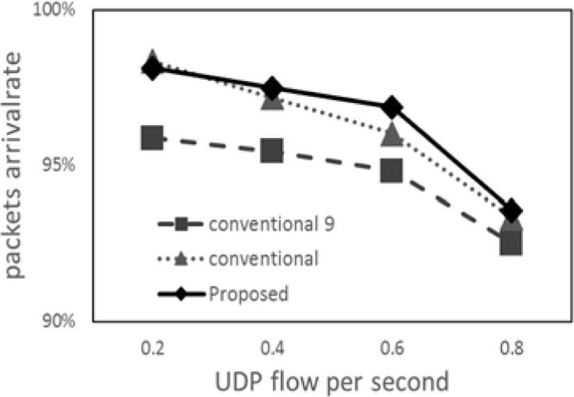
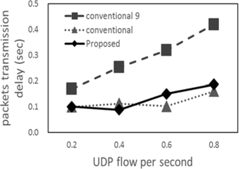
The results of the arrival rate and transmission delay of UDP packets are shown in Figure 4 and Figure 5, respectively. The notation “conventional 9” in these Figures is the conventional method with nine static Mas.
V. SIMULATION RESULTS
The proposed method and conventional method are better compared with the conventional method with nine static MAs from Figure 4. Further, in the case of the UDP flow frequency of 0.6 - 0.8 flows/s, the proposed method is better compared with the two conventional methods. The reason is that the load on the entire network is reduced because the area managed by the MA becomes appropriate by performing re-splitting. On the other hand, we can see from Figure 5 that the transmission delay of the two dynamic management methods is better compared with the conventional method with nine static MAs.
This is because of the two dynamic management method creates the suitable number of MA thus avoiding unnecessary control packets collisions.
VI. CONCLUSION
In this paper, we propose an enhanced method, in which the MA management area is properly determined based on the distribution of nodes in Location Based Routing.
From the results of the performance evaluation, the proposed method outperforms conventional methods in terms of packet delivery rate when network UDP flow frequency is high. The reason is that the load on the entire network is reduced because the area managed by the MA becomes appropriate by performing re-splitting.
In the future, it is necessary to devise the splitting mechanism in order to improve the performance.


