I. INTRODUCTION
The ubiquitous computing (UC) provides a useful context information for integrating capability in various scales. Such environments may therefore consist of devices ranging from personal devices to supercomputers. Also, various kinds of sensors and communication networks have been widely employed in smart car system. Moreover, new IT technologies such as human sensors (smart phone sensing), car-equipped vision/voice sensors, and visible light communication (VLC), are being merged to assist a driver safely and gather extensive information from the driving environment.
Among the growing applications of vision processing, vision-based vehicle verification algorithm for DAS has been concentrated to achieve remarkable for many years [1].
As one of the most promising applications of computer vision, vision-based vehicle detection for driver assistance has received considerable attention over the last many years [1]. We can consider the reasons why this field is blooming: First, the startling losses both in human lives and finance caused by vehicles accidents; Second, the availability of feasible technologies accumulated within the last 30 years of computer vision research [2], [3]; Lastly, the exponential growth of embedded computer performance has paved the way for computation of intensive video-processing mechanisms even though it is on a low-end PC [4].
The traffic accident rates in France, Germany, and the UK (among OECD members) have been reduced slowly after the1980s. However, the accident rate largely increased before the early 1990s, and then reduced after 1996 in Korea. The rate in recent has been reported to be 12.1 accidents per 100,000 vehicles on the road. Approximately 9 % are made from blind spot problem, where a driver cannot observe [5]. This is very high accident rate.
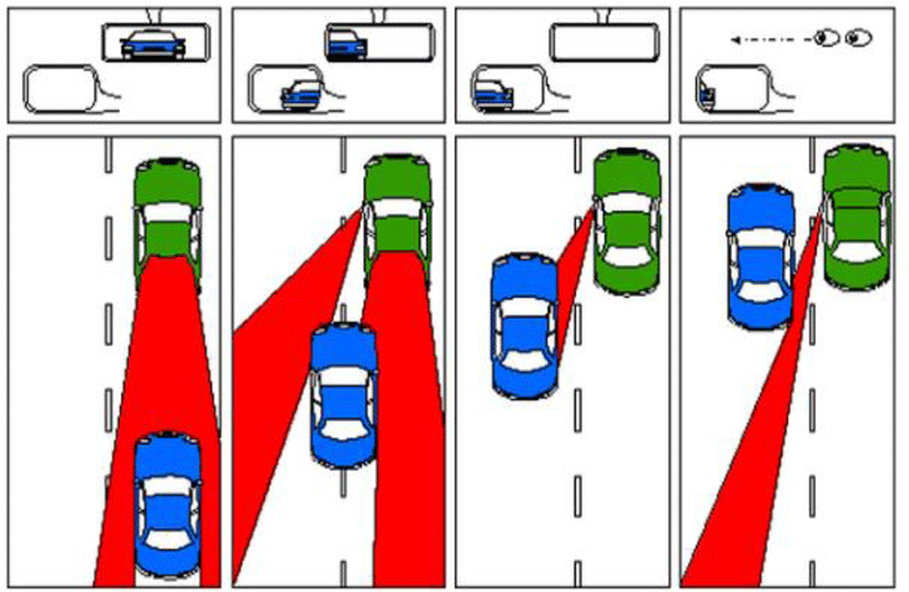
The blind spot refers to an area of the road that a driver cannot see using either the rear-view or side-view mirrors. Common blind spot areas are behind a vehicle on both sides. A vehicle in a blind spot cannot be seen by a driver.
Many automobile companies have developed new research programs to cope with the problem of blind spots. There are two major technologies: short-range radar and vision-based image processing. An image-based vehicle extraction system provides the processed information that can be intuitive for drivers to utilize [6]. The hot issue of image-based vehicle detection is to drive different driving environment. It can be necessary to extract candidate vehicles, which is robust to variation of the driving situation. To define vehicle features, symmetry, color, shadow, geometrical characteristics, texture, and headlights are employed to extract candidate vehicles [1]. Also, some learning methods are used to make a decision as vehicles after detecting candidate vehicles.
In this study, the feature extraction algorithm employes Haar-Wavelets [7], [8]. We employ the support vector machine (SVM) which is popularly utilized as a verification method [7], [8], [9]. An efficient method based on lane information has been suggested by Sun Zehang et al. [10]. Wu, Yao-Jan, et al. (2007) [18] based vehicle detection in a blind spot on lane information and vehicle shadow area detection. Lin Che-Chung et al. (2006) [14] and Balcones, D. et al. (2009) [11] used vehicle symmetry based edge feature extraction. Alonso Daniel, Luis Salgado, et al. (2007) [12] used edge extraction to define areas of interest. Also they made a structure of image division based on splitting and merging process. Song Gwang Yul et al. (2008) [13] proposed a method based on boundary extraction for the right and left sides of a vehicle, and extraction of the contacting region between the tires and the ground.
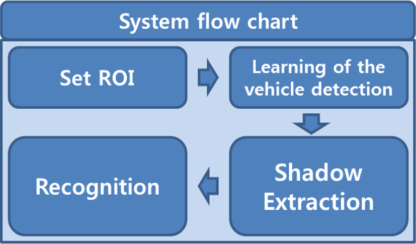
In this paper, we propose a new vehicle verification algorithm for the blind spot area using an imaging sensor. First, a region of interest (ROI) is set-up for obtaining candidate area. Through Haar-like feature, we train the vehicles. Then the shadow region is extracted for verifying whether candidate areas are approaching vehicles or not. This paper is organized as follows: Section 2 presents the overall system and related works. The proposed vehicle detection method is also defined in Section3. Section 4 discusses simulation results, and concluding remarks will be given in Section 5.
II. PREVIOUS RESEARCHES
We would like to define blind spot areas and present some previous researches according to stage of the processing in this section.
Figure 1 illustrates the problem of blind spot areas. A blind spot means a place that disappears from a driver’s view where side and rear vehicles are in specific locations. For extracting a vehicle in a blind spot, it is necessary to make recognition and verification scheme based on the approaching vehicles (from far to close in position). From the next subsection, the detailed procedure of vehicle extraction and verification scheme is explained.
Table I shows the reported studies on data learning. Data learning is for verification of true vehicles after detecting candidate vehicles. As mentioned, we employ Haar-Wavelets [9], [14] for the feature extraction. As we can see in Table 1, the support vector machine (SVM) is popular as a verification mechanism [9], [7], [14].
| Researches | Feature Extraction | Training and Classification | Main goal |
|---|---|---|---|
| Method [9] | SIFT + PCA | SVM | Various objects |
| Method [7] | Haar Waveletes | SVM | Person |
| Method [8] | Haar Waveletes | Online Boosting | Face |
| Method [19] | Local features | SVM | Various objects |
Reported studies for detecting vehicles and their tracking scheme are described in Table 2. We can categorize two detection approaches. One is a scheme based on lane information and the other is that without lane information. Usually, edge component is a good feature to identify vehicles [10], [15]-[18]. However, edge information may be not available in the detection stage because of change of the conditions of illumination such as weather when we drive, even though edge feature is very powerful [1]. Therefore, robust algorithm is inevitable to adapt various driving conditions.
| Researches | Detection of Candidate Vehicles | Tracking of Vehicle |
|---|---|---|
| Method [18] | - Lane Information Base -Road and Vehicle Shadow Area Segmentation |
- |
| Method [14] | - Lane Information Base -Symmetry Use of vehicle based edge feature |
- Use Motion vector estimation |
| Method [10] | - Lane Information Base - Edge information Use |
- Use Detection and Tracking, not General Detect then Track |
| Method [15] | -Symmetry Use of vehicle based edge feature | - |
| Method [16] | - Edge image detection for definition of interested area - Image division using split and merge |
- |
| Method [17] | - Boundary detection for right and left side of vehicle -Detection of the contact area of tire and road |
- |
| Method [7] | - Normalization perform of video brightness value -Investigation of shadow area - Vertical edge detection by Haar –like Feature |
- |
III. THE PROPOSED ALGORITHM
A blind spot is an area behind a driver’s normal field of vision that the driver cannot see using side-view and rear-view mirrors. For finding vehicles in a blind area, we can make recognition and verification scheme using the approaching vehicles (from far to close in position). The procedure of the proposed verification mechanism is presented in Fig. 2. A candidate vehicle is detected and confirmed based on the trained vehicle data in advance. The suggested vehicle verification method is powerful to be applied for various driving condition, because it is based on improvements from candidate vehicle verification with advanced training. Blind spot vehicle detection is based on shadows, Haar-like features, and AdaBoost classification [20].
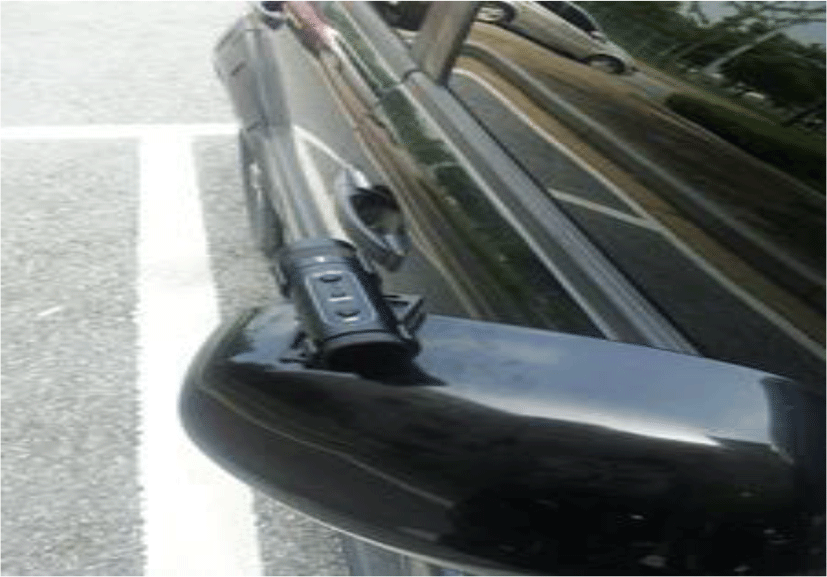
To achieve blind spot vehicle extration under all driving conditions, a single digital camera using the visible spectrum was set on the passenger side-view mirror (Fig.2). The digital camera had a CMOS 5.0M pixel capacity and operated at 30 frames per second with a 1920 1080 pixel resolution.
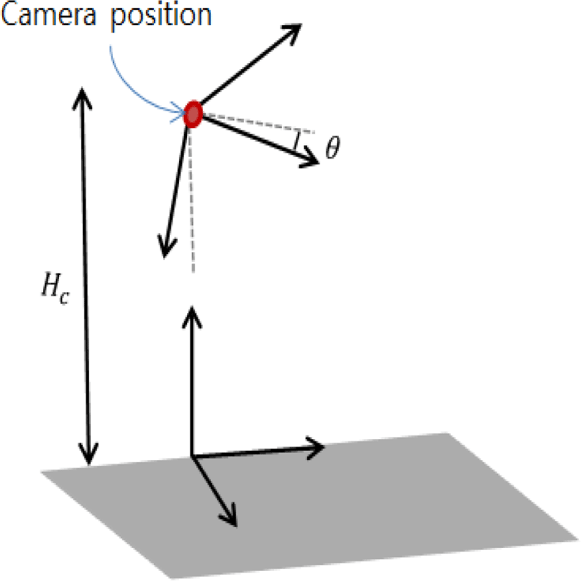
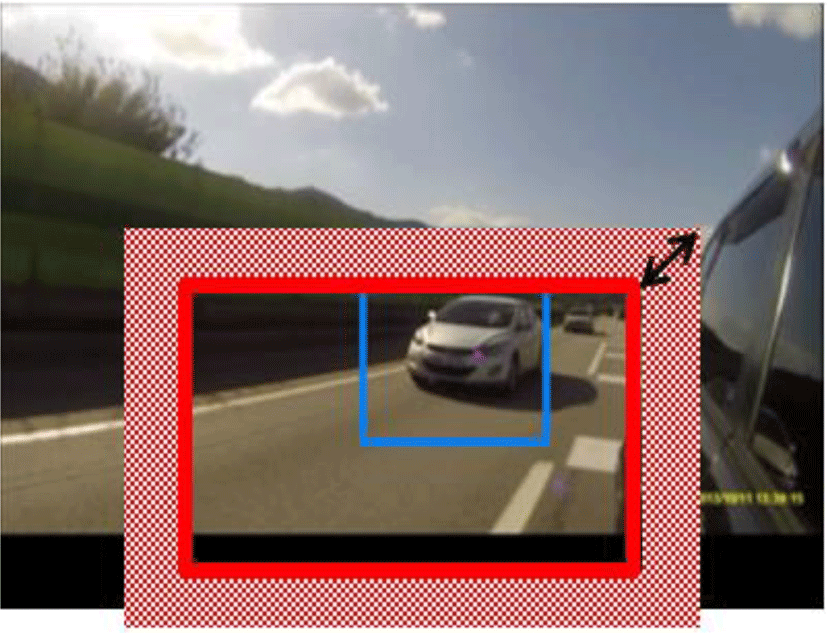
Vehicle extraction in the blind spot should only be needed in the area of interest. Figure 4 shows vehicle-mounted camera information. Hc is the height from the road surface to the camera (mounting height) and θ is the angle of the camera from the horizontal. The mounting height and angle of the camera, and information about the height and width of the image input image in the region of interest (The blind spot) were fixed. The ROI can be expressed as the following:
where
The region of interested (ROI) is defined using a set of four points. Eq. (1) is the region-of-interest formula for blind spot vehicle detection. Rx and Ry are four sets of data points derived from the ROI and imageh is the mean height of the input image. HC is the height of the camera, and θ is the angle of the camera. The product of these parameters defined the ROI and the input image showed the blind spot area.
The detector classifies any object in the image detection area as vehicle or non-vehicle. Therefore, the data training system needed only to characterize one class of object. Features of the front and sides of a vehicle after detecting vehicle were learned before applying the detection mechanism.
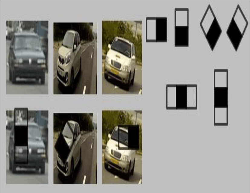
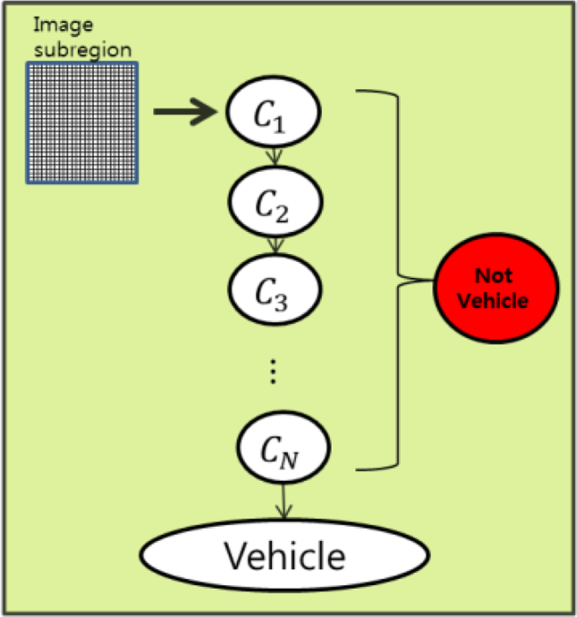
Figure 5 displays Haar-like features employed for initial learning. In the initial image data learning stage, we utilized 700 images of a vehicle and 1400 images of non-vehicles using Haar-like features. Figurre 6 illustrates to classify a vehicle or a non-vehicle based on the defined Haar-like features. In the first step, we reduced the number of candidate vehicles. If there exists a candidate image area in the final step, the image area can be verified into a valid vehicle. Using the Adaboost classifier, the number of iterations was experimentally optimized at 13. The feature value given by Eq. (3) is used for speeding-up calculation:
The Sacc (i, j) is the summation of pixel values in the corresponding area and I(i, j) are intensities of true vehicle area at pixel location (i, j) [21].
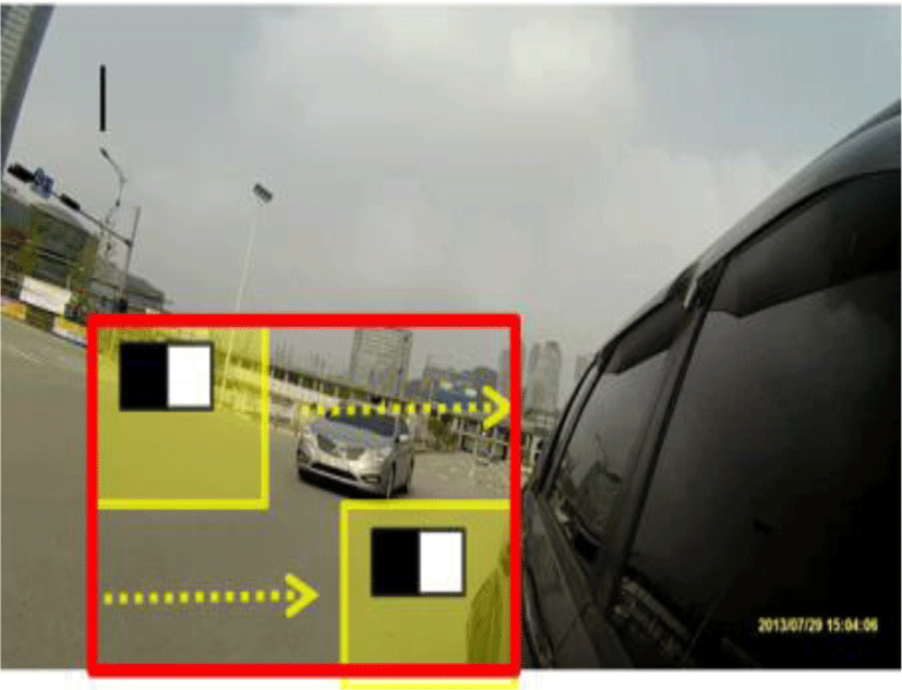
Figure 7 shows a haar-like feature of the vehicle through the process of detection of candidates shown in Fig. The red area is a blind spot area that is set to the region of interest (ROI). In this area of the vehicle candidate is iteratively estimated thereby.
After analysis of the vehicle candidate region, the process proceeds to shadow analysis. Figure 8 shows a vehicle for verification shadow extraction. A shadow area extracting the existing region of interest (ROI) proceeds through the area. Region of Interest (ROI) in the vehicle through a range of brightness values of the shadow component is extracted.
Eq. (4) for setting the brightness value of the surrounding area indicates the brightness component. The brightness of the final set and bwidthbheightis component of detecting region Eq. (5) shows the threshold (T) used to detect the shadows. Threshold uses the bwidth and bheight range of values of brightness with a total of brightness (I) of the surrounding.
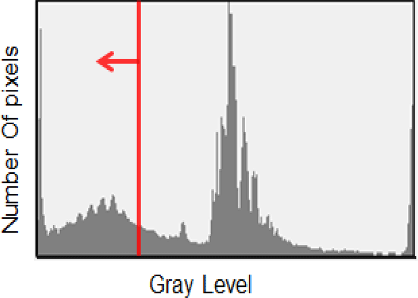
where bwidth and bheight are sizes of the area for brightness detection. In this work, we defined T1 as to be value of 10% in the gray-level histogram as shown in Fig. 9.
The detection area of a vehicle varies depending on the distance of the vehicle from the camera. If the distance between the vehicles is large, the detection area will also be large. Conversely, if the vehicles are close together, the detection area will be small. The detection area is measured using a 70x70 pixel minimum size and a 200x200 pixel maximum size. Detection is achieved by setting the threshold for the shadow area based on the value of the detected brightness and the size of the region.
For verifying candidate regions, we utilize a histogram from the luminance value. To do that, we convert the RGB color space to the YCbCr color space based on Eq. (6):
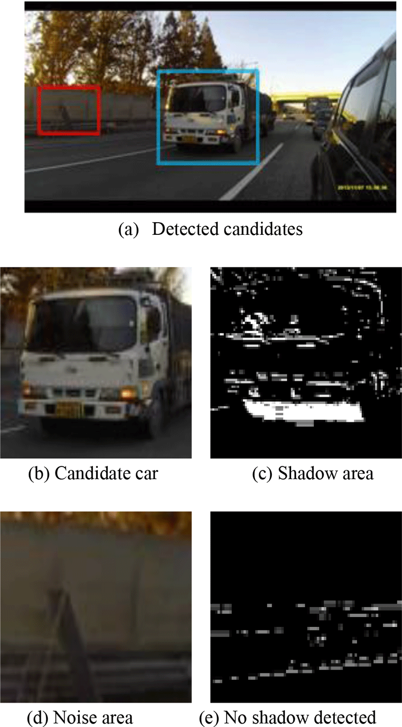
Candidate regions which are composed of a vehicle and non-vehicle are illustrated in Fig. 10(a). From this result, we can observe a significant difference from the components of shadow areas between the vehicle and the non-vehicle. Usually, the final result from a candidate vehicle can be disturbed by noise component as shown in Fig. 10 (a). Figures 10(b) and (c) show the detected regions for both a real vehicle and its shadow area in candidate region. In Fig. 10 (d) and (e), noise area is shown on the road. To verify true vehicle, shadow detection is useful as shown in Figs. 10(d) and (e) because of absolutely different property.
The area of vehicle detection is defined as the ROI and Eq. (7) is used to decide whether a block in the ROI is a vehicle. If there is pixel with a value over a defined threshold value (T2) in the 5×5 block area, Eq. (8) returns a value of 1. Otherwise, a value of 0 is returned. Using this defined block, the position of the vehicle area is determined.
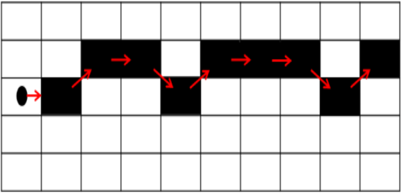
Since candidate blocks of a vehicle are present at the bottom of a vehicle image, the position of the candidate block differs depending on the distance between the camera and the candidate vehicle. The nearest block, which is connected horizontally in the group of candidate blocks, would be in the area of a vehicle. The block that is in the vehicle area starting from the bottom of the image is found first. Then, the trace of the block connected to the right and left is determined. More than 1 block should not be connected vertically.
Figure 11 shows the process of tracking adjacent blocks. If a block is connected with more than 9 other blocks, the image is designated as a candidate vehicle. The candidate vehicle height is determined based on the ratio of height to the horizontal length. Vertical and horizontal edge components are used to confirm the presence of a vehicle in the ROI. The vehicle region is determined and the vehicle block unit area is changed into a pixel unit vehicle area. The vehicle area is precisely determined using vertical and horizontal edge components. In the case of a lane change, vehicle identification in the blind spot varies depending on the vehicle locations.
A driver must judge whether or not a situation is normal. Differences in both the color component and region central point are used to confirm if the previous vehicle frame in the blind spot and the current vehicle frame are the same and represent the same vehicle.
Also the distance (Dcab) between the central points in different positions is computed as the following equation:
Using Eqs. (9) and (10), the candidate areas can be estimated as the weighted sum:
where ω is a weighting factor for considering the contribution of each term.
Eq. (9) is the formula for recognition and determination of a vehicle blind spot. Drrab is the difference in the average value of each component in HSV, Dcab is the distance between the central point in different positions. The smallest area of DTab is determined to represent the same vehicle in different locations using the front region of the suspect vehicle in the preceding frame compared with the same region in a later frame.
IV. SIMULATION RESULTS
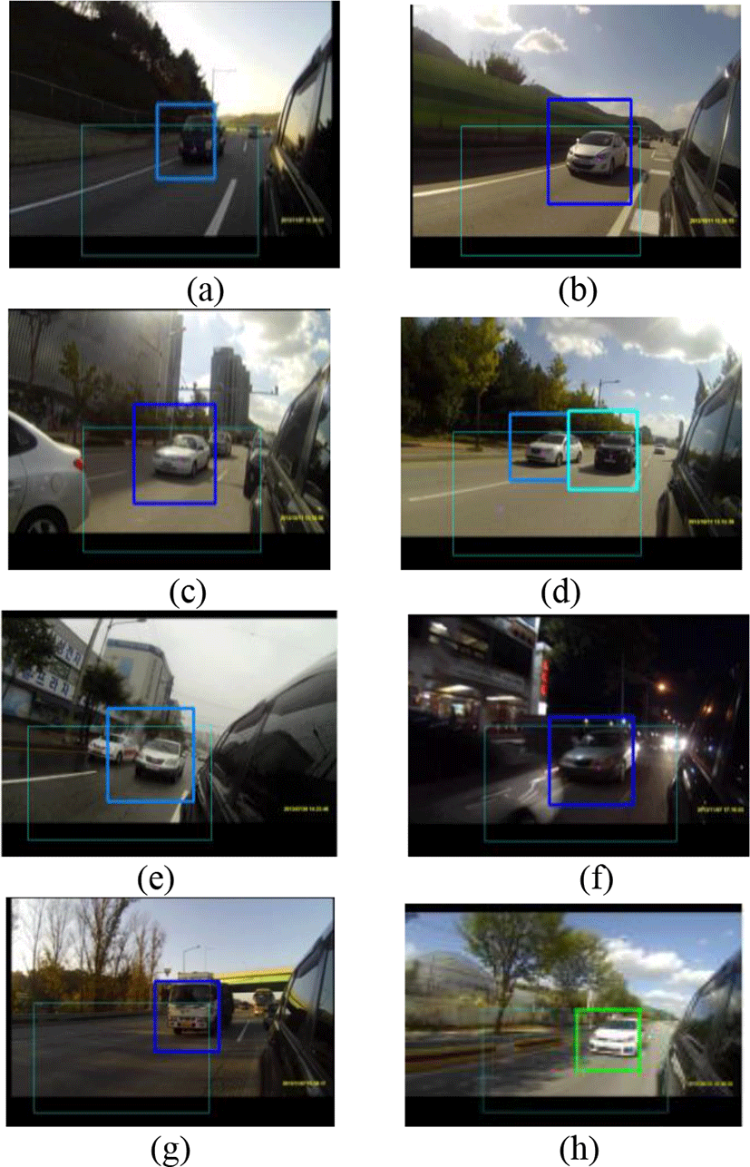
For evaluating the performance, various sequences captured with a backward-looking camera mounted on a side mirror were used representing different situations, including a highway, an urban road, and a rural road at different times of day. Figure 12 shows tested input sequences. Figures 12 (b), (h) and (d) show highway images. Figures 12 (a), (g) and (f) show images in a dark driving environment. Figure 12 (c) shows normal city driving. Figure 12 (e) shows a rainy driving environment. A test platform with CPU of 3.4 Hz and memory (RAM) of 8.00 GB, was employed for experiments. The image resolution was 128x128 using 700 learning images and 1400 learning images with non-vehicles.
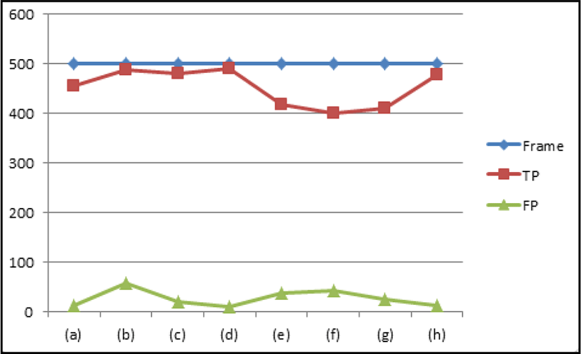
Table 3 displays recognition results with each test sequence. True Positives (TP) defines the correct detection of a true vehicle. False Positives (FP) denoted the incorrect extraction of a non-vehicle. From the results, we achieved 91.5% of the recognition ratio of true vehicles. This indicates that the suggested scheme give a good performance to detect true vehicles for blind spot areas. Under sunny driving conditions, a high recognition rate of 98.2% was obtained. However, in rainy or dark driving environments, the vehicle recognition rate dropped to nearly 10%.
Figure 13 shows false positive and true positive using the proposed algorithm. For almost sequences, we achieved very small values of False Positives (FP). For sequences (b), (e), and (f), values of False Positives were a little large. Although these results are caused by the low illumination (clouded day and night) and much amount of sun light, very small false positive and very high true positive were observed base on this result. This means the suggested scheme is reliable for detecting vehicles located in a blind spot area.
Table 4 shows the error and the blind spot vehicle recognition rates. The error rate was 3.2 percent with a 91.1% true positive (TP) rate for the entire vehicle. The processing time was based on 28 frames per second with 640x480 (VGA) video sequences. Thus, we can know that the proposed algorithm operates in real-time. In terms of error rate, 3.25% of false positive indicates very small error. From these results, we can deduce that the proposed scheme is very promising to provide an alarm for some approached vehicles in the blind spot area.
| Results | Car | Background |
|---|---|---|
| Car | TP: 91.1% | FP: 3.4% |
| Background | FN: 6.4% | TN: 88.4% |
V. CONCLUSION
An efficient algorithm for detecting vehicles located in a blind spot area has been proposed for smart imaging sensor-based system. The proposed algorithm uses information obtained from a rear-looking vehicle-mounted camera. We developed an real-time scheme to verify vehicles in the blind area based on adaptive shadow detection techniques. The proposed algorithm was able to adaptively cope with changes in illumination in the driving environment and performs well under varied driving conditions. The proposed algorithm can be applied for reducing the number of traffic accidents caused by blind spots. Also, the proposed technique can be extended to a smart sensor network in vehicle system.


