I. INTRODUCTION
Due to the advance in image processing systems and computer vision technology, there is an increasing demand for efficiently combining still images or video streams that are captured from different cameras in order to generate panoramic images. This procedure for combining multiple images into one single image is called image stitching [1]. The applications for image stitching range from driver assistance for smart cars, 3D mapping, defense/weapon systems, medical imaging, object or scene recognition, motion tracking, forensics and law enforcement to gaming and virtual reality – any vision system with multiple cameras that requires image processing and analysis [2] – [4].
Generally, image stitching algorithms can be classified into two categories – the pixel based [6] and the feature based [7] approach. The pixel based approach, also called the direct method shifts or warps the images relative to each other one pixel at a time, and finds the best alignment between the two images. The feature based approach consists of feature extraction, feature matching, and image blending steps, where distinctive features are first extracted from each image, and the common feature set that are included in both images will be identified. In addition, once a set of feature correspondences has been extracted, a feature set that will produce a highly accurate image alignment will be computed. The most widely used and efficient feature based image stitching algorithm is the scale invariant feature transform (SIFT) where feature extraction and matching can be realized with invariant to scale, rotation, and translation as well as partially invariant to affine distortion and illumination changes [8].
So far, image stitching has been mainly realized using software algorithms. However, although implementing image stitching algorithms with PCs are easy, the software based approach is slow, which critically limits the real time image data processing, i.e a general software image stitching algorithms can take more than 30-minutes for stitching a 1-minute video stream. Furthermore, as the image size increases and the image quality improves, software algorithms require humongous computing power, which makes the software based image stitching extremely inefficient and slow. Alternatively, hardware based image stitching schemes realized with field programmable arrays (FPGAs) or application specific integrated circuits (ASICs) can be faster than the software based approach, thus it is feasible to process real time image data. In addition, owing to improved VLSI technologies, the cost of the hardware based approach can be significantly lower than the software based image stitching schemes.
Especially, FPGAs are ideal for realizing different types of imaging hardware due to their programmability, compact size, and low power consumption [5]. However, even though hardware based image stitching is promising, simply using the existing image stitching algorithms to implement the hardware will not work, since this will end up with huge circuit blocks. As a result, developing a compact, fast, and low power hardware based algorithms and circuit blocks for FPGAs still remains a challenge that requires intense research efforts.
In this work, a FPGA based DoG filter using binary images that can be applied for realizing fast image stitching hardware is proposed. The proposed DoG filter is based on the zero-dimensional convolution using state machine LUTs, which can significantly improve the computation time compared to existing image stitching hardware.
II. FEATURE EXTRACTION USING BINARY IMAGES
DoG is a widely used filtering for image stitching, however it is not suitable to directly implement this with hardware due to complicated processing steps and humongous computations. In this work, to overcome this limitation, binary images that are composed of only two colors – black and white will be used. Although binary images are simple representation of the original images, they still preserve the global features of the original image such as contours, corners, edges, and lines which will make the image stitching algorithms to properly work.
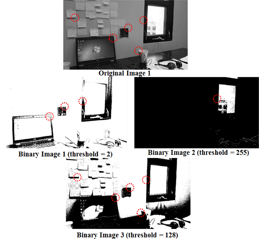
Figure 1 shows the gray scale (8 bit) input image is converted into binary images. The binary image can be obtained by comparing each pixel with a threshold level – usually the mid-level of the minimum and maximum pixel value, and representing the pixel value with either 255 (pixel intensity greater than threshold) or 0 (pixel intensity less than threshold), where 255 and 0 stands for the white and black level, respectively. As shown in Figure 1, if the threshold is too low (th=2), it eliminates the blob like objects (notepads on the wall). If the threshold is too high (th=255), a large number of essential feature points are eliminated. In this case, the threshold, 128 is suitable for our application since it still preserves useful edges and corner information. The dotted red circles indicate feature points of the image, where threshold levels can change the feature point information. For the threshold level of 2 and 255, only three and one feature points are preserved from the original image, respectively. For the threshold level of 128, all the feature points in the original image are preserved. In addition, by using binary images, the amount of data processed in the DoG filtering will be significantly reduced, which will enable a very fast computation for image stitching.
III. DOG HARDWARE IMPLEMENTATION
The proposed hardware implementation consists of three main modules: 1) binary image conversion, 2) zero-dimensional convolution with state machine, 3) LUTs.
The basic concept of extracting features, such as corner and edge detection are based on the identifying the rapid changes in pixel intensity. It can be computed by taking the derivative of the image: the difference between the previous pixel’s intensity and current pixel’s intensity
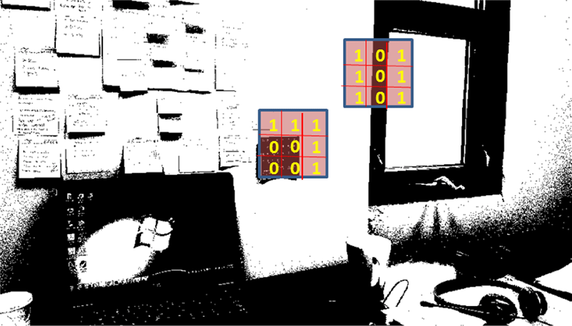
where Δx is always 1 since it is discrete pixel. As shown in Figure 2, the edge (3 by 3 window on the right) can be found where the intensity changes only along horizontally and the corner (3 by 3 window on the left) can be found where the intensity changes both along horizontally and vertically. In both cases, the derivative will result in 1 or -1 and such results are detected as feature points.
However, the problem with the derivatives is that it also amplifies the noises and accentuates high frequencies, thus the Gaussian Filtering (convolution with Gaussian Kernel: k by k matrix) has to be applied, which removes the noise by smoothing the image, similar to a low pass filter that convolves with its impulse response. However, for the SIFT algorithm, the computation time of the Gaussian Filter convolution module, consumes more than 70% of the entire computation time due to the heavy multiplications and additions [9].
If the Gaussian Filter is realized with a FPGA, the computation is proportional to W^2×K^2 where W is the image of width and K is the Gaussian kernel matrix dimension. However, since the Gaussian kernel is linear and symmetric, it can be separated into two 1-d Gaussian Kernel (vertical and horizontal):
This reduces computation time to 2 × W × K2.
After the Gaussian Filter (low-pass filter) is applied for blurring the noises, DoG filter should be used for enhancing the feature point of the blurred images. DoG is an approximation of LoG (Laplace of Gaussian) [1]. The DoG is given by:
where σ is the standard deviation of Gaussian distribution, k is the constant multiplicative factor and f(x, y) is binary input images. The Gaussian Kernel hσ is the discretized K by K matrix from continuous Gaussian function [12]:
The input image is repeatedly convolved with a multiple scale (k=1, 2, 3, n) Gaussian Kernel, and the difference produces the DoG; a subtraction of blurred image from a more blurred image.
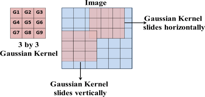
The conventional convolution of Gaussian Kernel can be computed by sliding the two dimensional Kernel matrix through the input images as shown in Figure 3. In this method, the horizontal and vertical convolution can be computed in parallel in a FPGA by utilizing the multiple shift registers so that multiplication and addition are computed concurrently. The tradeoff is that it requires more adders and multipliers.
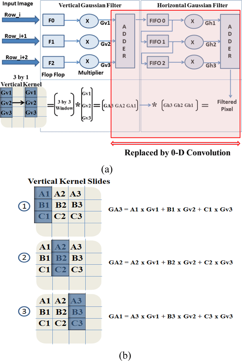
Another conventional method is using two 1-d convolutions as shown in Figure 4. The vertical Gaussian Filter can be obtained by sliding the 3 by 1 vertical kernel. The incoming pixel of input image from memory is stored in the flip flop first, then each pixel is convolved with the vertical Gaussian kernel [Gv1 Gv2 Gv3] concurrently in the FPGA by the multiplier and the adder. The output pixel from the adder, GA3 is computed when the vertical kernel slide is on the first position, where the three vertical pixels are multiplied by the vertical Gaussian kernel [Gv1 Gv2 Gv3]. The GA2 and GA1 are obtained from the same procedure, but with the different kernel position. Once [GA3 GA2 GA1] are stored in the FIFO in sequence, they will be convolved with the horizontal Gaussian kernel [Gh1 Gh2 Gh3], which produces the filtered output. The problem with this method is that the column Gaussian filter has to wait until [GA3 GA2 GA1] arrive in the FIFO after convolving with the vertical Gaussian Filter. This scheme still requires multipliers and adders. The drawbacks of this architecture can be eliminated by the proposed 0-d Gaussian filter with state machine and LUTs.
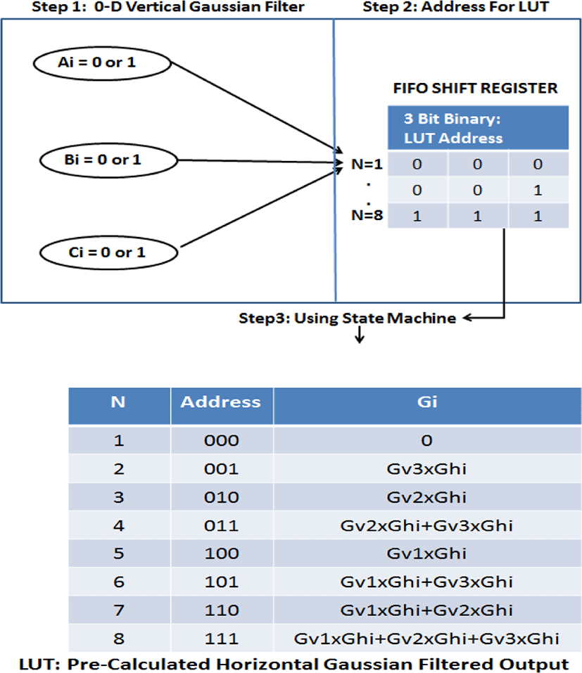
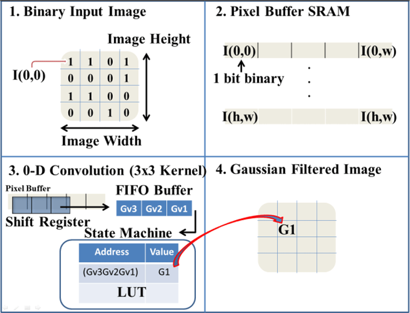
There are three steps in the proposed 0-d Gaussian Filter as shown in Figure 5. The first step detects the binary pixel data Ai, Bi, Ci, which is 0 or 1. The second step stores the three binary pixel data in the FIFO shift register and the stored three bit data becomes the address of LUT. The third step uses the State Machine to retrieve the pre-calculated Gaussian Filtered pixel output. The Gaussian Kernel values used in LUT for the pre-calculation are and . This generates the same results as the conventional Gaussian Kernel. However, it can achieve faster computation using binary image and LUT with 0-d convolution. In addition, the power consumption can be reduced by eliminating huge number of multipliers and adders. Since our binary input image has only one bit, either 0 or 1, the filtered pixel value after the vertical Gaussian Filter is same as the value of the Gaussian Kernel (if pixel data = 1) or 0 (if pixel data = 0). Thus, there is no multiplier required for the vertical convolution. Once we obtained the 1 by 3 matrix, such as [GA3 GA2 GA1] as shown in Figure 4, then it can be convolved with the 3 by 1 horizontal Gaussian Kernel [Gh1 Gh2 Gh3].
However, since the horizontal Gaussian kernel values are always constant and all the possible combination of multiplication for the vertical and the horizontal Gaussian kernels are known, the horizontal convolution is not required during the process. Fortunately, the possible combination of 1 by 3 matrix from the vertical Gaussian Kernel is N=8, and since the horizontal kernel values are always constant, the possible combination of final output will be still 8.
The possible combination can be known in FIFO when three binary pixel data (array of 0 or 1) from flip flop arrive in sequence. At this point, the final Gaussian filtered output can be known before the convolution with horizontal kernel. Thus, the conventional horizontal Gaussian filter can be removed from Figure 4(a). After 3 vertical Gaussian convolution sum data [GA3 GA2 GA1] are stored in the FIFO, the state machine uses these values as an address of the LUT (ie. 101). The multiplication of vertical Gaussian Kernel and horizontal Kernel values are stored in the LUT for each N, and the summation of each row in N is the pre-computed convolution of the data. Once the pre-computed convolution value Gi is retrieved from the LUT, the final Gaussian filtered output of the pixel is generated by summing the three consecutive Gi (for i=1,2,3).
IV. RESULTS
This work optimizes the hardware architecture of DoG algorithm by reducing the data size (using binary image input) and computability (using state machine and LUTs). The computability is reduced based on the big O analysis. The computation of matrix multiplication is O(n^3) and linear search for LUT is O(n). The proposed DoG hardware is realized using FPGA Altera DE2-115 board by storing incoming pixel in the SRAM, M9K blocks (embedded memory block in FPGA: 9k+ bits per block and support for shift registers, FIFO buffer and LUTs), DMA (Direct Memory Access) for write and read from the SRAM memory directly, 8-bit FIFO shift register for convolution, state machine, built-in peripheral IP module for SRAM Controller and VGA Interface, and NIOSII CPU for controlling the process and interface between our implemented DoG algorithm and memory.
Figure 6 shows the hardware implementation logic overview. In the first stage, the input image is converted to a one bit binary format (0 or 1) either from RGB or greyscale. The greyscale image (generally 8-bits) is converted to binary image with pixels either with 255 (white) or 0 (black). The threshold should be between 0 and 255. Later, 255 is replaced with a 1 for easy processing. The threshold value of 128 was selected for binary image in our hardware implementation. In the second stage, each one bit pixel of the binary image is stored in the FPGA SRAM. The size of SRAM is determining by the height and width of the image. In the third stage, the convolution is computed with 3 by 3 Gaussian Kernel. Our proposed 0-d convolution method uses the concept of two 1-d convolution, but the vertical and the horizontal Gaussian Kernel are replaced by 0-d convolution. Taking advantage of the binary format, the computation steps are reduced compared to the conventional 2-d convolution. For every cycle, three adjacent input pixels (0 or 1) are stored in the FIFO, and the state machine will use the three input binary pixel (0 or 1) as the LUT address to retrieve the pre-calculated convolution value. In the last stage, the output from stage 3 is Gaussian filtered and stored in the pixel buffer. The difference between the Gaussian modules (with different Gaussian Kernel) is the DoG. Finally, the output images are displayed via the VGA interface in FPGA.
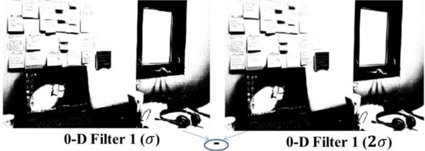
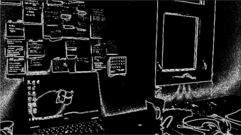
Figure 7 shows two 0-d filtered binary image with σ =1.4, where the right image is more blurred image with multiplying constant factor k, 2. Figure 8 shows the DoG filter results, which is the subtraction of two 0-d Gaussian Filter results. As shown, most of the features contained in the original images are reserved.
V. CONCLUSION
A binary image based fast Difference of Gaussian (DoG) filter using zero-dimensional (0-d) convolution and state machine look up tables (LUTs) has been implemented with a FPGA (Altera DE2-115), and the results have been verified. With the proposed approach for using binary images, the data size is significantly reduced compared to conventional gray scale based DoG filters, yet binary images still preserved the key features of the image such as contours, edges, and corners. Also, the proposed design eliminated the major portion of the adder and multiplier blocks that are generally used in conventional DoG filter hardware engines. Furthermore, this enabled fast computation time along with the data size reduction which led to compact and low power image and video stitching hardware blocks.


