I. INTRODUCTION
The quadruped robot is flexible to run on various regions with its optimized supporting structure and traction, decoupling the robot foot and the ground [1]. Currently, bionic quadruped robot with its stability and carrying capacity is more suitable than the biped ones and is more controllable and less complicated than the hexapod and eight-legged ones [3]-[6]. Therefore, the quadruped robot is an optimum selection with its flexibility, swiftness, bearing capacity etc. [7].
In the new century, the robot lab in MIT [8] proposed a new control theory, named model predictive control, which was used to obtain the support force through simplifying the kinetic model to solve the MPC problem, and to predict the motion in a gait cycle. In 2019, MIT developed Mini Cheetah using the improved the aircraft motor actuator, reached the highest performance at the cost control. The Mini Cheetah realized a back flips first time in the world by adding the improved algorithm of Whole Body Control (WBC) and torque control delicately for the self-invented motor.
In addition, robot vision is also a big problem for this kind of robot. Byung-Gyu Kim et al. proposed accurate target detection, fast image segmentation, video object target tracking based on deep learning [9]-[11]. Machine vision is also widely used in monitoring, agriculture, humanoid robots and other fields [12]-[14].
The present research discussed the motion of five bar linkages with parallel 8 degrees of freedom, foot trajectory algorithm and gait planning. The simulation model of single leg of quadruped robot would be constructed by Matlab software, combining the foot trajectory algorithm. Meantime, the principle and way of gait planning was investigated.
II. THE STRUCTURE AND KINEMATIC ANALYSIS FOR QUADRUPED ROBOT
The robot’s leg is designed as a serial mechanism according to bionics. A single leg consists of the kinematic chains with the drivers to be installed into each joint to transmit the movements gradually. The serial mechanism has some advantages, such as the simple structure, easy control algorithms, and large workspaces, but the large dead load and low bearing capacity are its disadvantages. The parallel mechanism is prevailing. It can drive two or more independent kinematic chains by the joints simultaneously. As each kinematic chain effects on the output of the robot, the motion error of each joint can be decreased and the force distribution on the parallel mechanism is more reasonable. The bearing capacity will increase by the parallel mechanism structure.
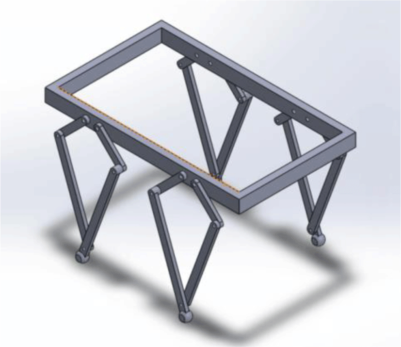
A five parallel linkage mechanism with two degrees of freedom is studied in this paper. A single leg is driven by two brushless DC motors. Each motor has an independent driver and the eight motors drivers are connected by CAN bus with the closed-loop control system in the central controller. Controlled by the independent position servo driver, the robot has an accurate trajectory. Because of the identical configuration for each legged-system, the quadruped robot has the interchangeability and easy to maintain. Mechanism schematic is shown in Fig. 1.
The kinematics of Robot establishes the relationship between the position and the orientation of each legged actuator. When determining the geometric angles of each joint in the setting coordinate system, the relationship between the relative displacement and velocity in each legged actuator will be established. The kinematic analysis is the foundation of the quadruped robot. It is one of the methods to solve the problems of the subsequent legged trajectory planning and gait design verification.
The kinematic analysis of quadruped robot includes forward and inverse problems [15]:
-
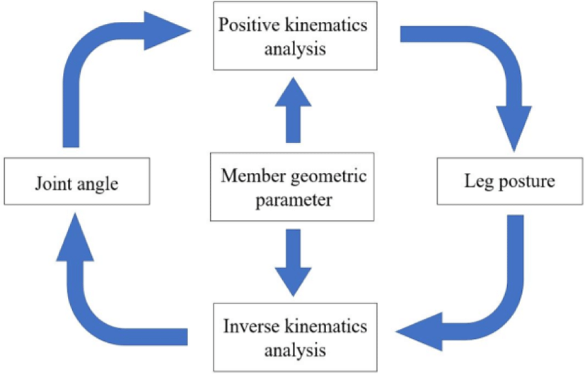
Forward kinematics analysis is to calculate the position, orientation and some other parameters of the legged actuator in the coordinate systems, when the size, type and other geometric parameters of the legged linkage mechanism and the angle of each driving joint are known.
-
Inverse kinematics analysis is to calculate the driving joint angle, the position and orientation of the leg in the coordinate systems when the geometric sizes of the linkage are known.
Fig. 2 shows the kinematic relationship between forward and inverse analysis.
The coordinate system of the robot body and the linkages is set up for the kinematic analysis. Then, the motion function between the linkages and the legged actuator is deduced. According to a 4*4 homogeneous coordinate transformation matrix to describe the spatial relationship between the linkages and the legged actuator, the homogeneous transformation matrix is established in work coordination systems. It can calculate the system parameters of the coordinates and motion speed for the legged actuators.
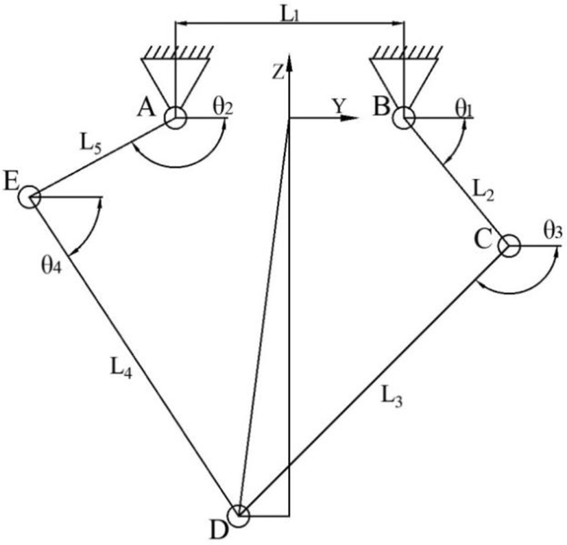
As shown in Fig. 3, global coordinate systems {O: Y, Z} is established for an arbitrary single leg. Since the drive joints A and B are connected with the body, the parallel five-bar linkages form the robot’s frame. Initially, the origin O is located on the centre of the frame. The total length of the frame is L1. Y-axis is along the horizontal direction and Z-axis is along the vertical direction. The origin of the moving coordinate systems of each linkage is fixed to the centre of the joint axis near one end of the frame, and the coordinates of point D of the leg are noted as (yD, zD). L2 and L5 is equal in value as the driving linkages. Similarly, the length of L3 is equal to L4 as the driven linkages. The direction angle of these four linkages, is noted as θi in the moving coordinate systems. Its initial position is on the Y-axis.
The coordinates of linkage BC are deduced as follows:
where θ1 is the angle between linkage BC and the positive direction of the Y axis, and L1 is the length of linkage AB.
The coordinates of linkage AE are deduced as follows:
where θ2 is the angle between linkage AE and the positive direction of the Y axis.
On the linkage CD and DE, the coordinates of the joints C and E are
where yc and zc are the coordinates of the joint C, yE and zE are the coordinates of the joint E, L2 is the length of linkage BC, and L5 is the length of linkage AE.
The length between the joints C and E is
According to the cosine theorem,
where ∠ECD is the angle between the line EC and linkage CD, ∠CED is the angle between the line CE and linkage DE, L3 is the length of linkage CD, and L4 is the length of linkage DE.
where θ3 is the angle between linkage CD and the positive direction of the Y axis, and θ4 is the the angle between linkage DE and the positive direction of the Y axis.
The homogeneous coordinate transformation matrix of linkage CD and AE is
By the homogeneous coordinate transformation matrix, the position and orientation of point D on the legged actuator.
From Eq.(14), the coordinates of point D in the global coordinate systems
where yD and zD are the coordinates of the joint D.
The position and orientation of the legged actuator can be determined by Eqs. (14)-(16), when the geometric parameters of the single legged linkage and the driving joint angle are known.
Two strategies can be used in the inverse kinematics solution for the parallel five-bar linkages. One is to directly calculate the driving joint angle by setting a triangle as an auxiliary line; the other is to establish equations for each kinematic chain independently according to the structure of the parallel five-bar mechanism with two branches, and solve all joint angles through equations.
The advantage of the latter method is that is a good foundation for the dynamic analysis, especially for the Jacobian matrix calculation. Although the dynamic analysis is not involved in this paper, these two methods are derived in detail. It can also deduce some equations for robot dynamics learning. The coordinate systems are set as in Fig. 1.
Firstly, to connect AD and BD, the length of LAD, LBD is
where LAD and LBD are the length of line AD and BD respectively.
In the triangle ΔADE, according to the cosine theorem, it can be deduced that,
where ∠EAD is the angle between linkage EA and the line AD.
In the triangle ΔBDE, according to the cosine theorem, it can be expressed as
where ∠CBD is the angle between linkage CB and the line BD.
Because there have multiple solutions to the pose of a single leg, the convex figure constraint should be added according to the actual motion,
In the triangle ΔABD, according to the cosine theorem, the following results can be obtained,
where ∠BAD is the angle between linkage BA and the line AD, ∠ABD is the angle between linkage AB and the line BD.
Finally, with these geometric relationship between the driving angle and each calculated angle,
The coordinates of point D on the sub-linkage noted as BCD are:
Simultaneously, on the sub-linkage noted as AED
where yD and zD are the coordinates of the joint D.
By solving each chain equation,
According to (25) and (26), the following results can be obtained:
where a and b are:
By these derivations, the driving joint angle can be calculated in real-time when the geometric parameters of leg mechanism are known.
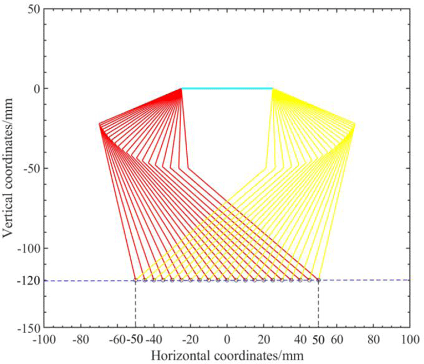
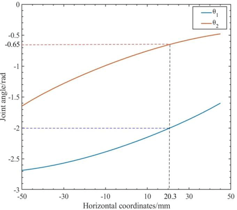
In order to verify the accuracy of the inverse kinematics equation, firstly the real-time compiler was used in Matlab for programming simulation. The length of the frame L1 was set as 30mm, the lengths of the driving linkage L2 and L5 were 50mm, and the lengths of the driven linkage L3 and L4 were 100mm. According to the model established by the inverse kinematics analysis, the linear trajectory constraint is applied to the legged actuator, for example zD =-120mm, and all outputs of the motion trajectory in the single leg linkage mechanism are derived. The simulation results of the position of the foot end are shown in Fig. 4. The legged actuator movement is a linear motion from yD =-50mm to yD =50mm. The function image about y-axis can be obtained by programming in the Fig. 5.
Then, the joint driving angle by inverse solution calculation was taken as the input of forward kinematics equation to solve the coordinate of the foot actuator. The angles of random point in Figure 5 curve, such as [θ1,θ2] = [2.0, 0.65] at [yD, zD] = [20.3, -120.0], are substituted into the forward kinematics equations (15) and (16). The corresponding foot end coordinates are obtained as [yD, zD]=[20.0,-120.1], which is approximately equal to the given coordinates of the point in the inverse solution formula. Thus, the accuracy of the inverse kinematics equation is verified, which lays a foundation for later foot trajectory planning.
III. TRAJECTORY PLANNING FOR THE LEGGED ACTUATOR
In the research of zero impact trajectory planning of foot, the most typical one is based on compound cycloid and high-order polynomial. In this paper, the zero impact trajectory planning algorithm of compound cycloid is studied and simulated to verify the effect of zero impact.
In the trajectory planning, the traditionally applied trajectory is cycloid locus, which can ensure that the robot has a small impact force when its leg lifting and falling. In order to minimize the impact forces in the swing phase limit position, the speed of the limit position should be controlled to near zero. If the dragging phenomenon of quadruped robot needed to be reduced in one cycle, a trajectory planning algorithm based on compound cycloid is proposed.
where S is the stride length, H is the leg lifting height, Tm is the swing phase time, and ys is the initial position of the swing phase.
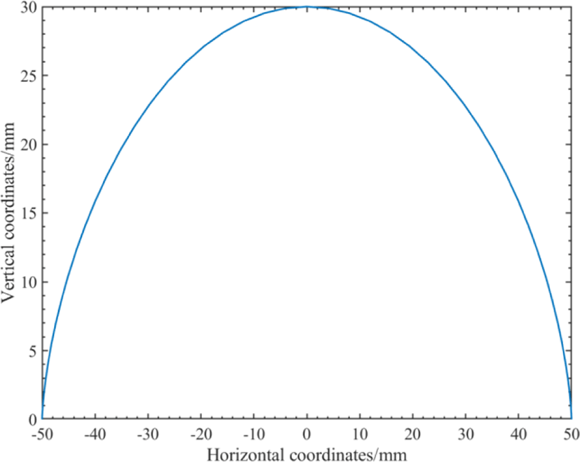
According to Eq. (33), programming and simulation in the Matlab real-time compiler make, the stride s input as 100 mm, the leg lifting height H as 30mm, the swing phase cycle time as 0.5s, and the initial position of the swing phase as - S/2 =-50, and the legged actuator trajectory of single leg swing phase is obtained, as shown in Fig. 6.
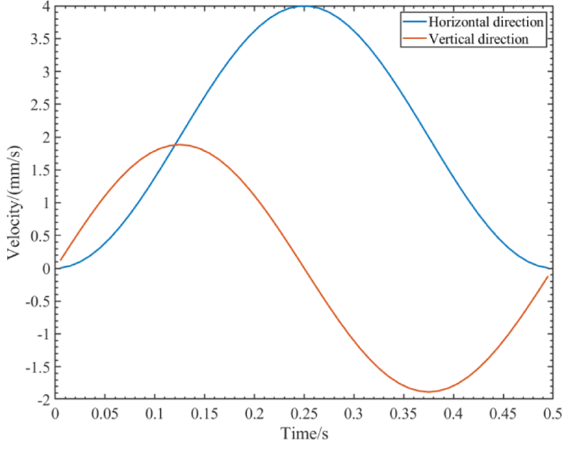
To derivative of foot displacement in y and z-axis, the velocity curve of foot along y and z directions are described as shown in Fig. 7. The velocity of the leg pose in the swing phase period is a smooth curve with zero starting and ending velocities, indicating that the foot motion is continuous and stable, which determines the feasibility of the zero-impact trajectory planning scheme based on the compound cycloid.
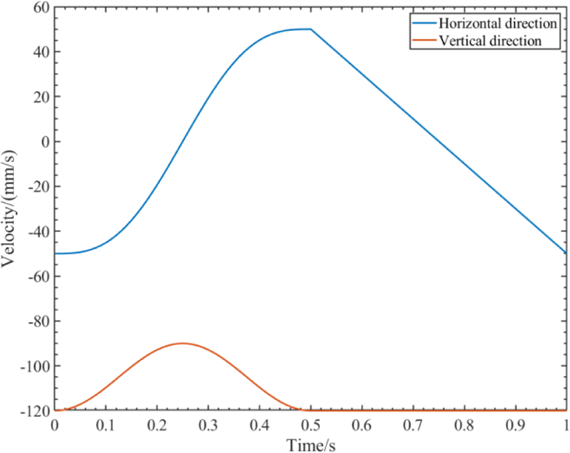
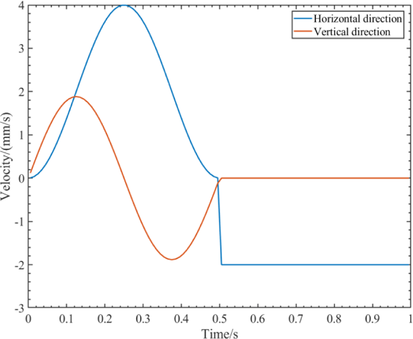
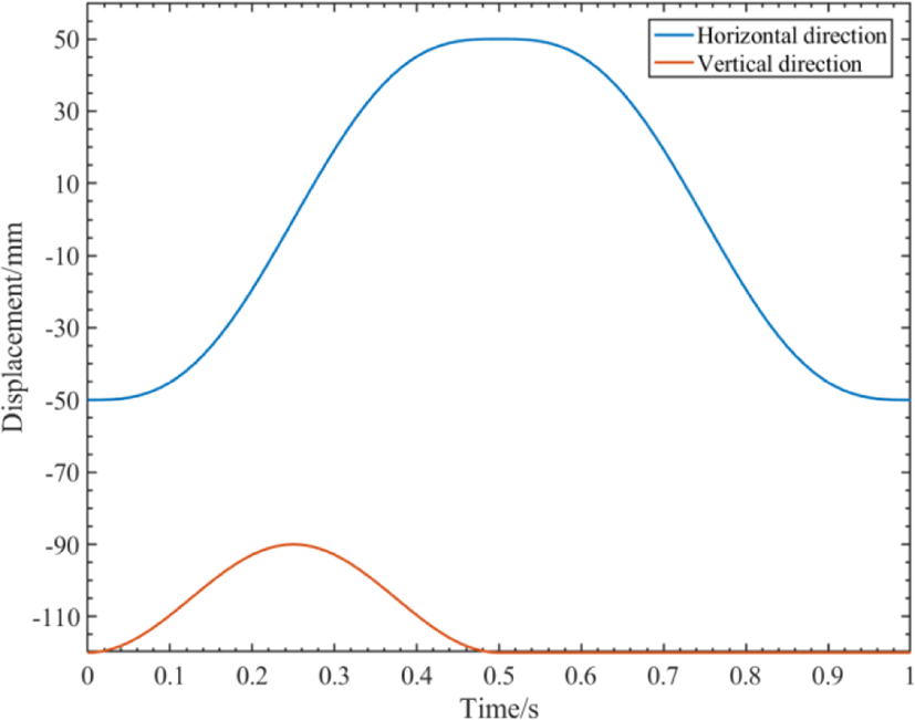
In Fig. 6, the feasibility of the zero-impact trajectory planning scheme is verified. The single leg gait cycle is set as TS, and the swing phase duty cycle is 50%. In order to ensure the smooth operation of the body, the support phase motion trajectory uses simple and uniform linear motion, and the whole gait cycle is simulated and analyzed. The curve of foot pose versus time is shown in Fig. 8, and the curve of leg with the maximum velocity is shown in Fig. 9.
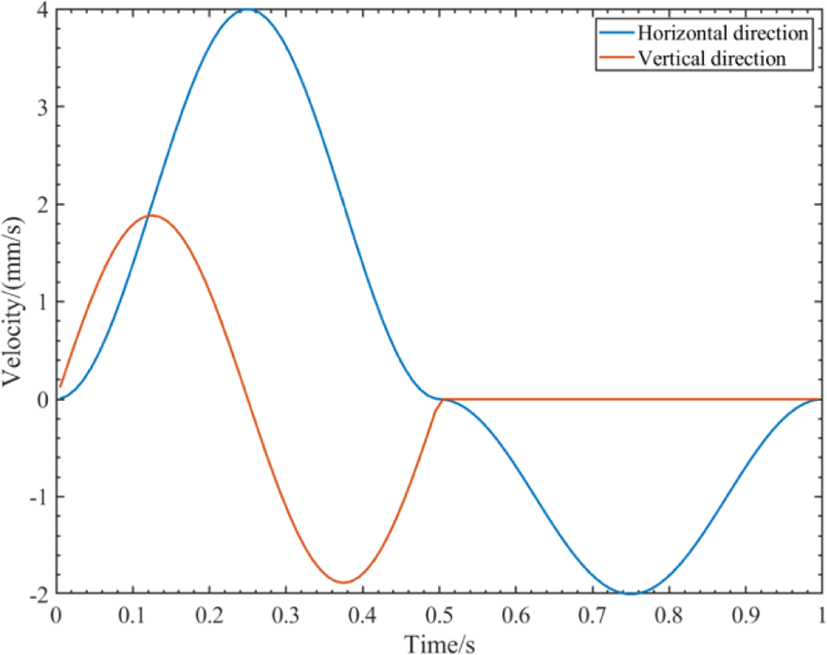
In Fig. 8 and Fig. 9, if only in the single swing phase or the single support phase, the displacement and velocity curves of the leg in the y and z directions are smooth and continuous. However, at the moment of switching between the swing phase and the support phase, the sudden change in velocity will cause a large impact between the foot and the ground, which will reduce the accuracy of the robot’s movement. In order to reduce the impact, a sine velocity curve is used to modify the motion of the support phase. The modified posture and velocity curves are shown in Fig. 10 and Fig. 11. In a complete gait cycle, the dis-placement and velocity curves are smooth and continuous, which the impact of foot movement is minimized.
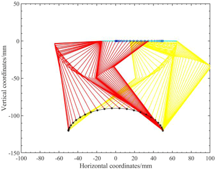
The designed foot trajectory of gait cycle was taken as the input parameter and put into the inverse kinematics model to obtain the motion state of the quadruped robot’s single leg in the gait cycle, as shown in Fig. 12.
In Fig. 12, the actual effect of zero impact leg trajectory planning can be directly seen through the trajectory of the linkage in the world coordinate system in the single leg gait cycle of the quadruped robot. The black dots represent the movement state of the foot, and the dots are denser near both ends, indicating that the feet have a lower speed and are less impacted at both ends. The blue dots show the movement state of the body, and the dots are denser near both ends, indicating that the body is moving at a lower speed at both ends.
According to the principle of relative velocity, the velocities of the feet are smaller than that of the body at this time, and the phase switching is more stable. The simulation results in Matlab show that the foot trajectory planning of gait cycle has good low impact performance.
IV. CONTROL SYSTEM AND SOFTWARE
General gait refers to the walker in the process of movement of the body to show a coordinated relationship. For a quadruped robot, the direct manifestation of this limb coordination is the sequence of leg lifting and leg dropping on all four legs during the entire gait cycle, which determines the walking mode of the quadruped robot. The speed and stability of quadruped robot are directly affected by its gait, so gait programming is the most important part in the research of quadruped robot.
At present, the research on the gait of quadruped robot is generally divided into two kinds. One kind is based on the bionics principle, according to the actual movement gait of the studied organism. The simulation research is carried out to generate the gait of robot. Another kind is based on the CPG (Central Pattern Generator) principle. By setting certain constraints and rules, it makes the robot simulate biological gait and makes dynamic changes according to the environmental variation. The gait of the robot is adjusted and optimized through continuous experimental records so as to obtain a fixed gait.
In this part, the principle of running diagonal trot gait of quadruped robot based on bionics is described, and the program is designed.
According to the principle of bionics, people apply the walking mode of animals to the field of robot and begin to study the gait of robot. In order to intuitively understand the gait of the robot, the relevant parameters are as follows:
-
Gait cycle: the time required for a quadruped robot to complete a cycle with one leg.
-
Swing phase: feet suspended and legs without load swing state.
-
Support phase: the foot ends touch the bottom and the leg loads support the body.
-
Duty ratio of supporting phase: the percentage of supporting phase in the whole gait cycle.
The diagonal Trot is the most common type of moving gait. In the diagonal trot gait, the supporting phase is 50% duty cycle, and the legs along the diagonal line of the body rise and fall in pairs.
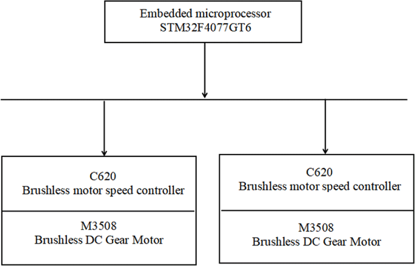
A parallel quadruped robot with 8 servo motors is designed in this paper. The quadruped robot will control itself and adjust by the feedback sensor on-time. In order to meet the requirements of small size and high processing speed, the embedded microprocessor STM32F407ZGT6 is selected as the main control, and the control circuit is composed of power management module and communication module. The hardware diagram of the main control system is shown in Fig. 13.
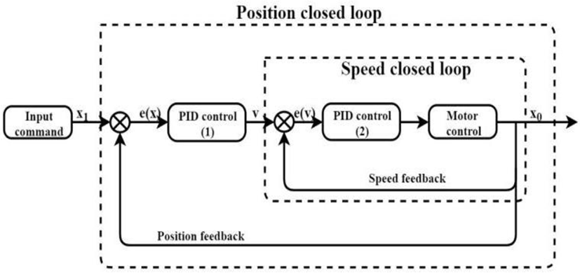
In the gait research of quadruped robot, the precision of joint drive plays a decisive role in the normal movement of the whole robot. The joint driving motor of quadruped robot is equipped with Dajiang m3508 brushless DC motor, which is controlled by C620 electronic governor. In order to ensure the accuracy and stability of joint rotation in the motion process of quadruped robot, it is necessary to use the servo control motor. The cascade PID algorithm which is used in servo drive is used to carry out closed-loop servo control of the motor. Servo drive control diagram is shown in Fig. 14.
In Fig. 14, the outer loop of the cascade PID controller is the position closed-loop, the input parameter of the position loop is the expected rotation angle of the motor, the output parameter is the speed of the motor, and the position feedback is adjusted according to the position information obtained by the encoder. The inner loop is a speed closed-loop, which adjusts the output speed of the outer loop and sends the control parameters to the motor, so that the motor can quickly turn to the specified angle. Compared with the single-loop controller, the cascade PID controller has better stability and reliability, and is more suitable for the control of the joint motor of quadruped robot.
The main driving functions of the motor are:
-
Motor data reception initialization function?
const get_M3508_Measure_Point(uint8_t i);
Set the corresponding variable to receive the position, speed and other feedback data of the motor.
-
PID initialization function :
void M3508_PID_angle_Init();
void M3508_PID_angle_ speed_Init();
Set PID parameters of motor speed and position closed loop.
-
Motor control function :
Data_Assignment(M3508_task *Task,float set);
Function built-in cascade PID control. Servo control is carried out by feedback data of motor state and set value.
float GM6020_PID_angle_calc();
float GM6020_PID_angle_speed_calc();
The function calculates the PID of the outer loop of position and the inner loop of speed respectively.
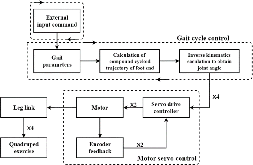
The users send control commands to the quadruped robot by using external controller such as the handle. The quadruped robot generates corresponding gait parameters according to the received control commands, and plans the trajectory of the feet based on the corresponding algorithm. Then the expected angles of each joint are generated by the inverse kinematics calculation formula. The joint angles are processed by cascade PID controller to form control parameters, which drive the M3508 brushless DC deceleration motor to complete a complete gait cycle movement of the quadruped robot.
The flow chart of Programming is shown in Fig. 15.
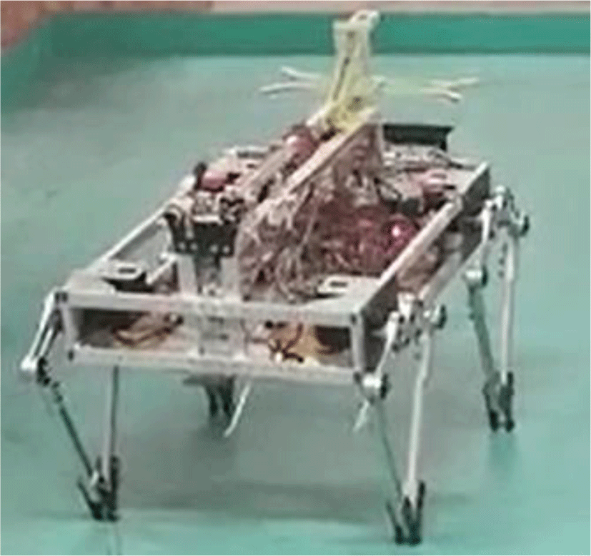
The model of the parallel quadruped robot is shown in Fig. 16.
V. CONCLUSION
In this paper, we have developed a novel leg structure of the quadruped robot with parallel five links and two degrees of freedom. The angle function of the leg joint is obtained with a relatively simple geometric method for kinematics analysis. Based on compound cycloid, the gait trajectory planning of quadruped robot was carried out. The trajectory planning process is optimized by using sinusoidal velocity curve to reduce the impact of switching between swing phase and support phase. Combined with the inverse kinematics model, the feasibility and practicability of this method are verified by the single leg simulation in Matlab. It provides an effective method for zero impact of quadruped robot’s feet in the process of motion. The cascade PID controller is used for servo control, which ensures the flexibility, accuracy and stability of the quadruped robot.
The quadruped robot with parallel five links and eight degrees of freedom can propose a solution for high-speed, high-precision and high-stability operation of the quadruped robot. It provides reference for the further development of the quadruped robot with parallel five linkages and 12 degrees of freedom.


