I. INTRODUCTION
Eye tracking refers to recognizing a gaze position on which a user gazes. Eye tracking has many applications. Typical applications include computer interfaces for the disabled, or military weapon systems such as sight guided TOW system. Recently, eye-tracking applications have seen further development for Internet shopping or reading ability verification.
Methods for estimating the position of gaze include a method using the head, a method using the eyes, and a method using both. In the method using the head, the position of the gaze is determined according to the position of the head, but it is difficult to detect minute changes in the gaze. The method of using the eyes is estimated based on the geometric characteristics and relationships of the gaze, iris, and pupil. The position of the gaze is determined by the spatial positional characteristics between the pupil and the glint caused by corneal reflection and is tracked through the position, shape, and distortion of the iris [1-2].
The most studied eye-tracking technology is based on the relative position between the glint of the cornea and the pupil. This method uses the glint as a reference point under the condition that the user’s head is fixed and finds the gaze direction using the vector from the center of the pupil to the glint. However, this method has a problem in that a large error occurs even with a small movement of the head. Therefore, the degree of freedom of the head poses the biggest obstacle to eye tracking.
In addition, since glint requires additional lighting, it is difficult to apply the eye-tracking system to a computer in a natural state because it cannot be obtained from a universally used webcam [9].
The algorithm proposed in this paper uses both the head and eyes but does not use glint. A small camera embedded in laptops, tablets, or computers enables the eye-tracking system. This paper proposes an algorithm that overcomes many of the limitations in eye tracking mentioned above and enables eye tracking even in low-resolution images obtained from webcams.
This is an eye-tracking solution that incorporates the ET-DR and kNN algorithms. With the same text, 100 Korean students ran studies on computers with and without the algorithm. The algorithm enhanced eye-tracking accuracy by about 240% in the experiment.
This paper describes the theory and practice of eye tracking, as well as the suggested algorithm. Furthermore, the problem of pupil reflection is addressed, as well as the way for overcoming it and the remedy. The improvement rate was calculated by comparing the algorithm-applied eye-tracking system in real time to the non-applied eye-tracking system.
II. EYE DETECTION AND FACE DETECTION
The first step in eye tracking is to find the eyes. In general face detection process, eyes are used widely among face components for tilt correction and normalization of the face. The eyes are characterized by a dense concentration of black pixels so that the eyes area appears distinctly darker than surrounding areas. However, there are many cases in which eyes are not detected due to hair, eyebrows, black-rimmed glasses, etc.
The face must be detected first to find the eyes. Ten dark areas in the face areas are set as candidates.
The center of the region where seven or more candidate groups are concentrated is determined as the pupil region. If the candidate group is isolated, eye area detection is attempted again.
Eye detection using Glint is easily accomplished. Two separate IR lights are required as shown in Fig. 1 [9]. The position of the gaze is determined by the spatial location characteristics between the pupil and the glint caused by corneal reflection, and the location of the gaze is tracked using the position, shape, and distortion of the iris.
To get an eye image, a camera equipped with an infrared filter and two infrared light sources is required to create a reflection point on the corneal surface to determine the gaze point on the monitor.
While eye detection is straightforward, it has the disadvantage of requiring a separate device to be installed and is expensive. Since it does not meet the purpose of using a general-purpose camera pursued by this paper, the general method using Glint is excluded.
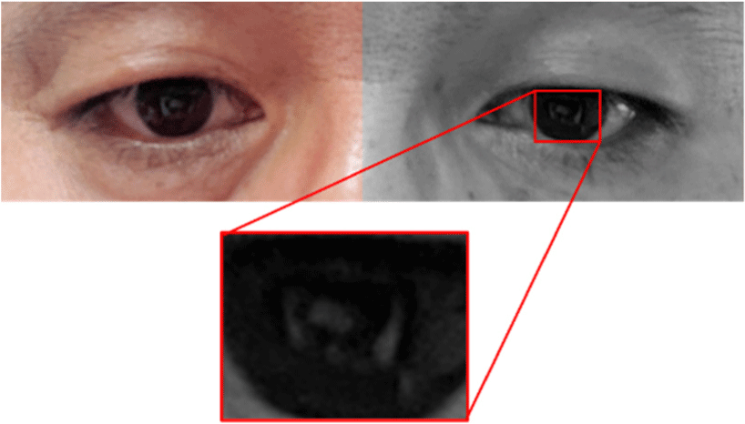
The front of the Android tablet has a built-in camera. It is difficult to detect the pupil of the eye without infrared light due to most built-in cameras having low sharpness since there is no glint from infrared light as shown in Fig. 2. Rather, a noise reflector is projected on the pupil area, which becomes a factor that interferes with pupil detection.
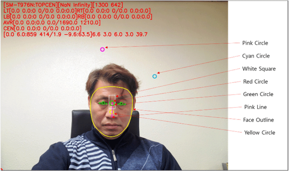
Since it is difficult to predict the direction of gaze when the pupil is not detected clearly, it is predicted using various auxiliary tools, as shown in Table 1 and Fig. 3.
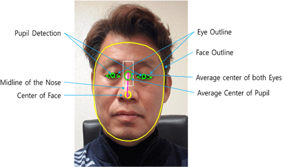
Fig. 4 illustrates how eyes and pupils can be found when utilizing an auxiliary tool.
The average pupil center can be used to find the pupil. First, the average value of the two eye outlines is calculated using the center point as a reference. The average center of the two eyes is determined using this central point, and the average center of the pupil is determined from this.
At this moment, based on the red circle in Fig. 4, the green circle moves in accordance with the pupil’s position, and the green circle can be used to determine the gazing point at which the gaze arrives.
Face detection requires the user to look straight at the camera. The frontal face contour is retrieved, and a yellow circle is formed in the middle to identify the tilt and rotation angle of the face [8].
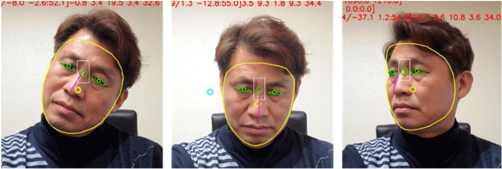
Because the yellow circle is always in the middle of the face contour, the up, down, left, and right rotation angles of the face may be calculated based on the location of the yellow circle, as shown in Fig. 5.
After extracting the two eye areas, the images are tilt corrected and normalized using the center locations of the two eyes. First, the image’s slope is calculated using the retrieved center angles of the two eyes.
When the coordinate value of the center of the left eye is (x, y), the inclination angle θ of the face is obtained as in equation (1).
After correcting the slope of the image using the obtained slope angle of θ, the size of the face is normalized.
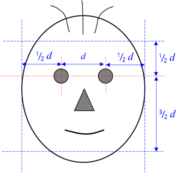
When d is the distance between the centers of the eyes, normalize the size of the face by 1/2d on both sides of the eyes, 1/2d above the eyes, and 3/2d below the eyes as shown in Fig. 6.
The area of the eyes is first taken from the tilted or rotated face, and then the face is normalized using processes such as tilt correction.
The outline and central point of the face, the average center of both eyes, the center line of the nose, and the average center of the pupil should all be used to determine gaze points. When the user glances at a certain location on the monitor, each of these characteristics are retrieved. These retrieved characteristics are depicted in Fig. 7.
Using these features, it is possible to calculate the position of the eyes by the rotation and tilt of the face and the gaze point accordingly.
The eye tracking algorithm presented in this paper does not perform calibration, does not use glint, and uses only a low-resolution webcam. In this case, there is an advantage that it can be used on all smartphones as well as laptop computers or tablet PCs without any additional devices.
The difficulty in implementing this algorithm is that it is difficult to accurately find the pupil, and that real-time calibration is required according to the head’s high degree of freedom. In addition, the fact that the criterion for the central point of the eye is variable also adds to the difficulty in implementation [7].
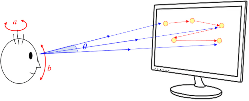
Therefore, the gaze is tracked by combining the measured facial tilt and eye angle. However, because the head has a high degree of freedom, such as the face rotation angle a b and gaze rotation angle in Fig. 8, instability and distortion of the gaze point ofte n occurs. A latency arises while attempting real-time calibration to acquire a gaze point from a moving face due to the time necessary to determine the gaze point. Because the latency causes the gaze to drop, eye tracking is made impossible.
Two algorithms, kNN and DR, were used to overcome this. kNN and DR are algorithms that are mostly used for positioning. The DR algorithm, for instance, is turned into PDR and is mostly utilized for indoor navigation. This positioning algorithm was improved and applied to eye tracking in this paper. Similarly to how the DR algorithm was transformed into PDR and used for indoor navigation, Eye Tracking Dead Reckoning (ET-DR) was developed and used for eye tracking.
III. ALGORITHMS
kNN is an essential algorithm used in indoor positioning. Furthermore, kNN is perhaps the most frequent and straightforward method of indoor positioning. It can produce excellent results in environments with a high density of APs. kNN is basically a nearest neighbor (NN) when k =1. It shows the user’s location at one of the reference points of AP. It is based on the characteristics of RSSI since RSSI degrades with distance. Here, if RSSI of AP is replaced with gaze point, it can be applied in eye tracking as it is [6].
The usage of kNN in positioning have been quite popular since it does not need any kind of signal modelling while other techniques like trilateration which estimates distance between transmitter and receiver for location estimation requires signal modelling. However, kNN’s performance deteriorates with decreasing number of APs. If the number of APs are limited, it does not provide reasonable accuracy. The number of k in kNN is determined by the number of accessible APs. Because a smaller or larger amount of k can affect accuracy in both directions.
While kNN in positioning is strongly dependent on the number of APs, kNN in eye tracking is more accurate since it utilizes the number of gaze points rather than APs.
The kNN algorithm has the property that the results vary substantially depending on the distance-measuring method utilized. A typical example is the Euclidean Distance, which is the most commonly used distance measure. It is the shortest distance in a straight line between two observations.
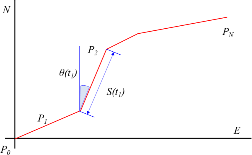
Dead Reckoning (The DR) algorithm is used to estimate indoor/outdoor locations based on hardware equipped with IMU sensors, and PDR applies this concept to pedestrians.
DR is the process of calculating the current position of a moving object using a previously determined position or fixation, then incorporating estimates of speed, direction of travel, and path over elapsed time.
The principle of Pedestrians Dead Reckoning (PDR) is according to the pedestrians walking distance and heading of the walking period to reckon current position of pedestrian from a known previous position. Assuming the previous position is (E(t1),N(t1)), the current position is (E(tn), N(tn)), heading during the walking period is θ(ti), the distance is S(ti), the relation of the positions is as in equation (3) [3].
The accuracy of the position depends on the accuracy of the initial position and the accuracy of the gaze travel distance and direction during the calculation process. The starting point of first sight may be used to collect the first location information, and the accuracy fulfills the requirements [6].
The gaze travel distance is calculated by combining the gaze velocity and the head rotation angle. The gaze direction and head rotation also influence the heading.
Unlike DR in positioning, DR data in eye tracking is generated by humans hence, gaze must be estimated using a logical and geometric method without an IMU sensor. Thus, the following principles were established and the DR algorithm was updated so that it could be applied to eye tracking.
-
- Sentences are read from left to right.
-
- If more than 80% of the sentence length has been read or the remaining part is a predicate, the sentence is determined to be read complete.
-
- When sentence reading is completed, the same sentence repeat reading is excluded. Therefore, when the reader has read the sentence to the end, the gaze will be changed to the next sentence.
-
- Area of Interest (AOIs) are limited to nouns or verbs. There is no case where an AOI is a predicate, a conjunction, or a preposition.
Gaze estimation starts with pupil detection. When a pupil is detected, it is combined with the facial tilt angle to determine the look direction. However, the front camera on most Android-based tablet PCs does not have a sufficient resolution to detect it [8].
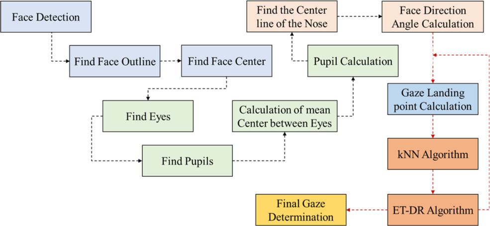
As illustrated in Fig. 9, the pupil is detected by calculating the average center of both eyes based on the center of the face and nose, as well as the average center of the pupil.
Finding a face is the initial step in eye tracking. Then, it finds the face’s contour, center, and eyes in that sequence. Finding the pupil is challenging since this algorithm employs a webcam instead of a professional camera. As a result, the pupil is anticipated using a variety of calculations, and the average center between the eyes is computed.
The predicted pupil is determined at the same angle as the eye, and this is combined with the calculated orientation angle of the face to determine the gaze.
It is an algorithm that determines the final gaze by combining the determined gaze, kNN, and ET-DR algorithm. The sequence is illustrated in Fig. 11.
As illustrated in Fig. 11, the pupil is quantized and shown on the monitor after it is detected using the average center of both eyes according to the center of the nose and the average center of the pupil. The quantization method used the kNN algorithm presented above.
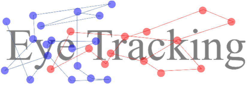
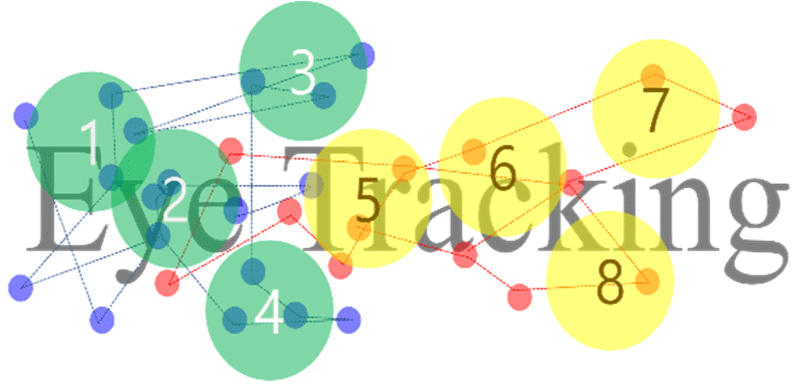
Fig. 14 shows the quantization of the gaze point for the word ‘Eye Tracking’ on the monitor. The gaze point is shown by the small blue circle and the red circle in Fig. 11. The blue circle represents the ‘Eye’ gaze point, while the red circle represents the ‘Tracking’ gaze point. If the blue circle leans towards ‘Tracking’ during the glance, but the continuous gaze point returns to the ‘Eye’ position, it is cut off by the kNN algorithm or regarded as the ‘Eye’ gaze point. The red circle also momentarily passed over the word ‘Eye’, but returned to ‘Tracking’ consistently, hence this is considered as the gazing point of ‘Tracking’.
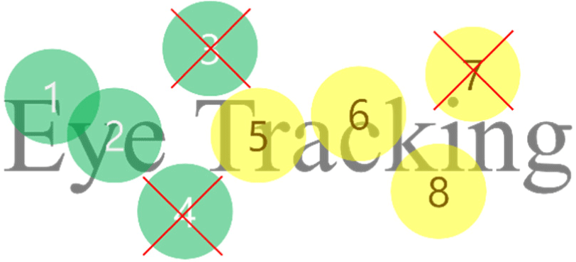
These are quantified as green circles 1, 2, 3, 4 and yellow circles 5, 6, 7, 8. Green circles 1, 2, 3, 4 represent gaze point quantification for the word ‘Eye,’ with gaze determined as 1, 2 and 3, 4 discarded. Yellow circles 5, 6, 7, and 8 represent gaze point quantization for the word ‘Tracking.’ Determine gaze as 5, 6, 8, and discard 7.
Eye tracking is the physical tracking of the gaze trajectory based on eye movement. Eye movements are not continuous processes, but rather discontinuous processes in which quick saccades and slight fixations occur repeatedly. When reading, the eyes do not move smoothly and continuously to the right, but rather stay in one spot for a set length of time, move fast in the direction of the text, stay at that point again, and saccade again, repeating the process. Most of the information about the eye is obtained during a fixed period [5].
A fixed point refers to a state (appr. 200−250 ms) in which the pupil stays in a specific area such as an object, image, or a sentence. Fixation does not imply that the movement of the gaze is completely stopped. This is because even if the gaze is fixed in one place, a slight tremor of the eyes occurs [2]. Three types of eye movements occur at this time. Tremor, drift, and micro-saccade are three of them. Therefore, micro-saccades can occur even within a set time period. When the barrier between micro-saccade and general saccade is erased, it is difficult to distinguish a period called fixation in reading. This is due to the fact that many micro-saccades are occurring even during what is typically considered to be a stationary phase.
Second, a saccade is the quick movement of the eyes from one glance to the next. It is an eyeball movement between gazes as a movement that quickly changes the gaze direction from one objective to another, as well as indicating the speed of glance movement and the acceleration starting point. The saccade movement of the eyeball in daily activities such as visual exploration or reading a book is the most significant eye movement in rapidly centering an image of an object in the surrounding area [4].
Third, the gaze path generally refers to a path that receives stimuli from images and moves. This is the largest category of eye movements, including fixed and momentary movements and patterns during image reception. Furthermore, parameters such as eye blink, pupil size, pupil diameter, and so on are used to observe eye movements.
IV. EXPERIMENTS AND APPLICATIONS
This study proposed the kNN and ET-DR algorithms for optimizing eye-tracking. The ET-DR algorithm is a reinvention of the existing DR algorithm as an eye-tracking method. Because DR is already a widely used algorithm in navigation systems, this type of eye-tracking application experiment is quite relevant.
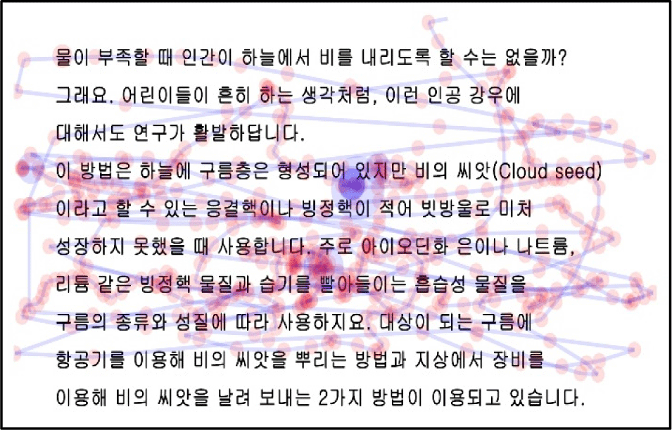
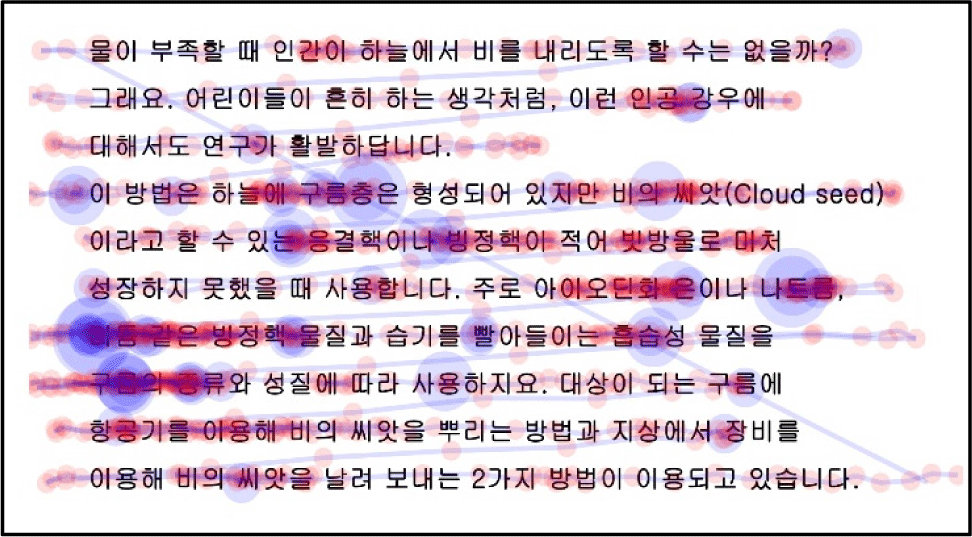
Eye tracking using simply a low-resolution camera and no real-time calibration or IR light for glint proved extremely inaccurate. As illustrated in Fig. 15, the eye tracking result prior to applying the algorithm lost directionality and orderliness.
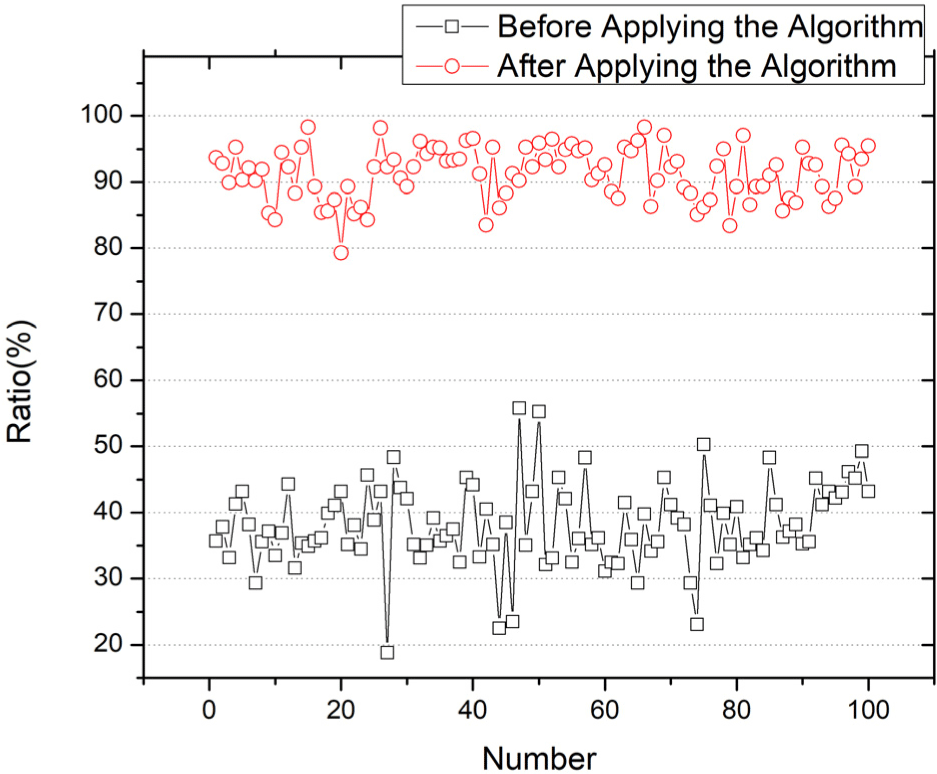
An experiment with 100 participants obtained an average accuracy of gaze and gaze points of 38.1%. In terms of the experimental approach, the test participants read the text aloud while looking at it, and the application logged the text of the gaze point where the present gaze stays throughout time. Table 2 compares the times of speech and text, as well as the agreement rate when they matched.
An application based on kNN and the ET-DR algorithm was experimented upon the same conditions. As in the previous example, 100 participants read aloud the text, and the program logged the text of the gaze point where the gaze is now positioned, as well as the time.
The experiment resulted in a gaze point accuracy of 91.3%. The point of sight in Fig. 15 is quite complicated and inconsistent while explaining the results, and saccades, escapes, and discontinuities are repeated.
On the other hand, in the case of Fig. 16 where the algorithm is applied, the continuity of reading flows naturally, and the fixation of the gaze and the saccade are clearly displayed. In addition, it guarantees clear certainty to extract the region or AOI where the gaze stays.
The proposed ET-DR algorithm seems to have played its role well when applied to eye tracking as well as navigation. In particular, the term ‘ET-DR’, which was used experimentally and was created temporarily, has sufficient qualifications as an algorithm that can enhance eye tracking in that respect.
Eye tracking improved performance by about 240% by applying ET-DR and kNN algorithms. Accordingly, it can be directly applied to smartphones as well as webcams and tablets. In addition, The accuracy of this test result was quoted from the result measured through an experiment by the Korea Laboratory Accreditation Scheme (KOLAS), an internationally accredited certification body.
In Fig. 17, it can be validated by visually checking how much the accuracy has improved by plotting the gaze point accuracy before and after applying the algorithm on the same graph.
V. CONCLUSION
This study proposed a strategy for overcoming the limitations of existing eye-tracking systems’ generalization. The problems of existing eye tracking systems that hinder generalization include the method of using glint, the hassle of real-time calibration, the difficulty of fixing the head, the need to use a high-resolution camera, and the need for infrared lighting.
This paper obtained successful results by applying algorithms that no one has tried on eye tracking. This provided a new development path and broadened the area of eye-tracking system development.
The fatal weakness of not using infrared lights, high-resolution cameras, and glints is that the pupil cannot be found and the size of the pupil is unknown. It is also difficult to find the gaze.
Without resolving these three issues, eye tracking was previously impossible. The importance of this study is that it gave a fresh approach to solving three problems. Applying an algorithm from a completely different solution such as navigation to eye tracking appears to be a ground-breaking endeavor.
There are limitations to estimating gaze using a low-resolution camera without a reference infrared light such as Glint. Furthermore, there is a limit to analyzing the pupil because the user’s image is reflected in the pupil without infrared lighting, so additional research is needed in this area.


